Samsung Refrigerator Main PCB Failure: Complete Diagnostic Guide
When your Samsung refrigerator stops working, it’s easy to assume the main control board has failed. However, true main PCB failures are actually less common than homeowners think. Before you spend $300–$500 on a replacement board, you need to systematically rule out the power supply, individual sensors, and the inverter board (which controls the compressor separately). This guide walks you through professional diagnostic steps that will either confirm a genuine board failure or point you toward the real culprit.
Where Is the Main PCB in a Samsung Refrigerator?
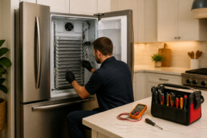
Understanding the location of your control board is the first step. Most Samsung refrigerators have the main PCB mounted behind an access panel at the rear, typically near the top of the unit. You’ll find it by unplugging the refrigerator, removing the rear cover panel (usually held by a few screws or clips), and looking for a rectangular circuit board with visible connectors and capacitors. The board will have a label with a part number starting with DA92 or DA94.
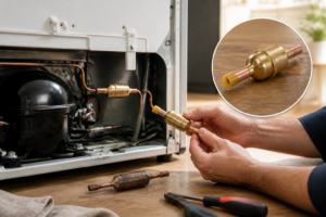
It’s critical to note that Samsung refrigerators often have two separate control boards: the main PCB (which controls displays, sensors, and overall logic) and the inverter board (which manages the variable-speed compressor). The inverter board is typically located near the compressor at the bottom rear of the unit. Confusing the two during diagnosis is a common mistake that leads to unnecessary repairs.
Quick Answer: Is It Really the Main PCB?
Before we proceed with diagnostics, know this: if your refrigerator has power at the outlet, receives some voltage at the board, and any component is working (display lights, compressor running, fan spinning), the main PCB is likely not completely dead. Genuine main PCB failures result in total loss of all functions powered by that board. Partial failures—where the display works but the compressor won’t run, or vice versa—usually point to a specific failed component on the board (a relay, capacitor, or connector) rather than the board itself, or they indicate a problem with a secondary board like the inverter.
Symptoms That Point to Main PCB Failure
The following patterns suggest a genuine main control board issue:
- Completely dead unit with confirmed power at the outlet: The refrigerator draws no current; nothing lights up, no compressor noise, no fan activity. You’ve verified the outlet works by plugging in another appliance.
- Display is dead, but the compressor runs: The cooling system operates on a timer, but you cannot read the temperature or control settings because the display receives no power from the board.
- Multiple unrelated systems fail simultaneously: The ice maker stops, the display becomes unresponsive, the water dispenser quits, and the fan stops—all at once—even after a power cycle.
- Random resets during operation: The display freezes, the unit powers off unexpectedly, or all settings reset to defaults multiple times per week.
- Error codes that persist after power cycling: The refrigerator displays an error code (like “PC ER” or “FF ER”) that remains even after unplugging for 10 minutes and restoring power.
Symptoms That Usually Are NOT the Main PCB
Before you test further, eliminate these common false suspects:
- Refrigerator not cooling, but compressor is running: This is almost never the main PCB. Check airflow between fridge and freezer, inspect the defrost system, and verify the evaporator fan is spinning. See our guide on testing the motherboard on the Samsung RF28R7351SR for compressor-related diagnostics.
- Ice maker alone is not producing ice: The ice maker module, water inlet valve, and water supply line are the usual culprits—not the main board. Refer to Samsung RF28R7351SR ice maker problems for targeted troubleshooting.
- Water dispenser not working: Check the water inlet valve and filter first.
- One display segment not illuminating: A single dead LED or LCD segment suggests a display module issue, not main PCB failure.
Step 1: Perform a Power-Cycle Reset
Many apparent “board failures” are actually firmware lockups that clear with a full power cycle. Follow this procedure exactly:
- Unplug the refrigerator from the wall outlet.
- Wait a full 5 minutes. (This allows all capacitors on the board to fully discharge.)
- Plug the refrigerator back in.
- Allow 3–5 minutes for the unit to boot and initialize.
- Observe whether the display illuminates, compressor engages, or any sounds/activity resume.
If the unit springs back to life, you’ve solved the problem—the board was in a lockup state and is still functional. If nothing happens, proceed to Step 2.
Step 2: Access and Read Error Codes (Self-Diagnostic Mode)
Samsung refrigerators have built-in diagnostics accessible via button combinations. The exact sequence varies by model, but the most common method is:
- Press and hold the Freezer and Fridge buttons simultaneously for 3–5 seconds.
- Listen for a beep; the display should enter diagnostic mode and show a series of numbers or letters.
- Press the Freezer button to cycle through error codes.
- Write down any codes displayed (examples: “PC ER” = power control error, “FF ER” = freezer fan error, “RF ER” = refrigerator fan error).
Note: Some models use Energy Saver and Fridge buttons instead, or a different combination entirely. Check your model’s service manual (available through Samsung’s support site or appliance repair forums) for the exact sequence. If the display is completely dark and unresponsive, you cannot access these diagnostics, which is a strong indicator of main PCB failure or power delivery failure.
Error codes are invaluable because they pinpoint which component the board is failing to communicate with. A code tied to a specific sensor or component means the board itself is likely still functioning—the problem is with that external part or its connection.
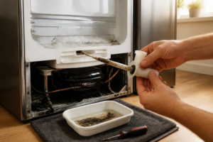
Step 3: Visual Inspection of the Main PCB
⚠️ Safety Warning: Before touching the board, ensure the refrigerator is unplugged. Capacitors on the main PCB can hold a dangerous electrical charge even when unplugged. Wait 5 minutes after unplugging, and do not touch any large cylindrical components (capacitors) directly.
With the unit unplugged and the rear access panel removed, visually inspect the main PCB for these failure indicators:
- Bulged or leaking capacitors: Look for cylindrical components with a domed or split top, or visible liquid seeping from their base. Failing capacitors are the most common cause of partial main PCB failure.
- Scorch marks or burn spots: Dark burn marks on the circuit board surface indicate a component has overheated or shorted. This is a definitive sign of failure.
- Blown onboard fuse: A small cylindrical or rectangular component that appears blackened, cracked, or physically broken indicates a power surge has damaged the board.
- Burnt relay or relay coil: Relays are small switch components; if one appears charred or the plastic housing is melted, it has failed.
- Moisture or corrosion on connectors: White, green, or blue crusty deposits on connector pins indicate corrosion from humidity. This is common in humid climates and can prevent proper signal transmission.
- Loose or disconnected connectors: Verify all ribbon cables and connector plugs are fully seated and not visibly loose.
If you observe any of these issues, you have confirmed physical damage to the board. Document with photos before proceeding with replacement.
Step 4: Voltage Checks with a Multimeter
This is the definitive electrical test. You’ll need a digital multimeter (inexpensive models are available at any hardware store).
Test Setup
- Unplug the refrigerator.
- Remove the rear access panel to expose the main PCB.
- Plug the refrigerator back in (the board will be powered, but no cooling will occur immediately because the compressor requires specific timing commands).
- Set your multimeter to the AC voltage (VAC) setting, typically indicated by a “V~” symbol.
Check Input Voltage
- Locate the main power input connector on the PCB. This is usually a two-pin or three-pin connector where the power cable from the outlet enters the board.
- Carefully place the multimeter probes across the two pins (black probe on ground/neutral, red probe on the live pin).
- You should read approximately 120 VAC (or 230 VAC in some regions).
- If you read 0 VAC, the board is not receiving input power. Check the power cord and outlet first.
- If you read the correct voltage, proceed to the next test.
Check Output Voltage (DC Rails)
The main PCB converts AC input into DC (direct current) for internal components. These are called the 12V and 5V rails.
- Switch your multimeter to the DC voltage (VDC) setting, typically indicated by a “V—” symbol.
- Locate the 12V output connector. This is often labeled on the board or found near the voltage regulator components.
- Place the black probe on a ground pin (usually a black wire) and the red probe on the positive 12V pin.
- You should read approximately 12 VDC (acceptable range: 11.5–12.5V).
- Repeat for the 5V rail, which should read approximately 5 VDC (acceptable range: 4.75–5.25V).
Interpreting Your Results
- Good input (120 VAC) + Good output voltages (12V and 5V present): The board is receiving and distributing power correctly. A lack of function points to a logic failure (a fried component on the board) or a failed sensor/external component.
- Good input (120 VAC) + No output voltages (0V on all rails): The board’s internal voltage regulator has failed. The board cannot power its own circuitry. This is a genuine main PCB failure.
- No input voltage (0 VAC) detected: The problem is upstream: check the power cord, outlet, and any thermal fuses in the power distribution system before condemning the board.
If you confirm good input but no output, you have electrically proven the main PCB is defective. If you confirm both input and output voltages are correct, the board itself is likely functional, and you should investigate external sensors, connections, and the inverter board.
Step 5: Distinguish Between Main PCB and Inverter Board Issues
Many compressor problems are incorrectly blamed on the main PCB when the actual culprit is the inverter board. Here’s how to tell them apart:
Inverter Board Symptoms
The inverter board controls the variable-speed compressor and is separate from the main PCB. If you hear rapid clicking sounds from the compressor area every few seconds, and the compressor never actually starts to run, the inverter board has likely failed. The main board is sending signals correctly, but the inverter cannot translate them into compressor motor commands.
Main PCB Symptoms (Compressor-Related)
If the compressor never engages and you hear no clicking or any sound from the inverter/compressor area, the main PCB is not sending the start command. This points to main PCB failure or a defective compressor start sensor.
Testing the Inverter
You can perform the same voltage checks (Steps 4) on the inverter board connector to verify it receives power from the main PCB. If the main PCB outputs 12V to the inverter connector but the compressor will not start and you hear clicking, the inverter board has failed independently. If the main PCB sends no voltage to the inverter at all, the main board likely has a failed relay or control circuit.
Step 6: Confirm the Main PCB Part Number
Before purchasing a replacement, you must identify the exact board in your unit. Samsung has produced multiple revisions of the main PCB for each refrigerator model, and installing an incompatible board will not work.
- Locate the white or silver label on the main PCB itself (not the refrigerator model label).
- Record the part number. It will look similar to: DA92-00623A, DA94-02914C, or similar (DA92/DA94 series).
- Do not rely solely on your refrigerator’s model number (like RF28R7351SR) to order a replacement. Boards were revised mid-production.
- Search for the exact part number and your refrigerator’s model number together to confirm compatibility before ordering.
- When the replacement arrives, compare its part number label to the original—they must match exactly.
When to Replace the Main PCB
Replace the main PCB if:
- You confirmed good input voltage (120 VAC) but zero output voltages (12V and 5V rails read 0V).
- Visual inspection revealed burnt components, bulged capacitors, or scorch marks.
- You’ve ruled out power supply, sensors, and inverter board issues using the steps above.
- Error code diagnostics confirm a failure in the main board’s internal logic (not a sensor or external component).
⚠️ Safety Warnings
Electrical Safety: The main PCB operates at 120 VAC. Always unplug the refrigerator before accessing the board. Even after unplugging, wait 5 minutes—capacitors on the board can hold a dangerous charge. Do not touch large cylindrical components directly. If you are uncomfortable working with electrical components, contact a licensed appliance repair technician.
Water Damage Risk: When testing with a multimeter while the unit is plugged in, keep your multimeter and hands away from any water drainage areas or condensation. Do not use a wet multimeter or allow moisture near the board.
Frequently Asked Questions
What is the difference between the main PCB and the inverter board?
The main PCB (control board) manages the refrigerator’s overall logic, displays, temperature sensors, and sends commands to other systems. The inverter board is a separate component that controls only the compressor’s variable speed. You can have a functional main PCB and a failed inverter, or vice versa. Always inspect both if the compressor will not run.
My Samsung refrigerator display works perfectly, but the compressor never starts. Is it the main PCB?
Not necessarily. A working display indicates the main PCB is functional. The likely culprits are the inverter board, a defective compressor start relay, a faulty compressor temperature sensor, or the compressor itself. Use the voltage checks in Step 4 to verify the main board is sending 12V output to the inverter connector. If it is, the inverter has failed. If not, the main PCB has a failed relay or control circuit.
Can a power surge damage only the main PCB and leave everything else working?
Yes. A lightning strike or utility surge can damage specific components on the main PCB (like the voltage regulator or a relay) while other systems continue to function. If you’ve experienced a power surge and are now seeing partial failures, the main PCB is a likely culprit. However, surge damage may only affect one circuit on the board, in which case replacing a specific component (if you have soldering skills) may be an alternative to full board replacement.
How much does a replacement main PCB cost?
A genuine Samsung main PCB typically costs $300–$500, depending on the model. Labor for installation by a technician adds another $150–$300. Because of this cost, professional diagnosis is worth the investment—a $150 service call that rules out the main PCB and identifies a failed $50 sensor saves you hundreds of dollars.
Is it safe to replace the main PCB myself?
Replacing the main PCB is a straightforward task for someone comfortable with basic appliance disassembly: remove the rear access panel, unplug all connector cables, unscrew the old board, install the new one, and reconnect. However, diagnosing the problem (the focus of this guide) requires more care because it involves testing live electrical circuits. If you proceed with replacement, ensure the unit is unplugged during the physical swap. Many homeowners replace the board themselves but hire a technician to diagnose the original failure.
Recommended Tools
Digital Multimeter
Nearly every diagnosis in this guide comes down to a continuity or voltage reading, and a basic digital multimeter handles all of them. Check current pricing on Amazon.
Appliance Repair Tool Set
A dedicated appliance tool set with nut drivers, Torx bits, and panel spudgers makes the disassembly steps in this guide far easier and prevents scratched panels and stripped screws. Check current pricing on Amazon.