Samsung ME18H704SFS Door Switch Replacement: Complete Repair Guide
The Samsung ME18H704SFS is a premium over-the-range microwave that combines convection cooking with a built-in ventilation system. However, like all microwave models, the door switches can fail over time, leading to operational problems. This guide will walk you through identifying, testing, and replacing the door switches on the ME18H704SFS with professional-level accuracy.
Understanding Door Switch Failures on the ME18H704SFS
The ME18H704SFS uses a three-switch safety system to prevent microwave operation when the door is open. Understanding how these switches work is essential before attempting repairs.
Why Your ME18H704SFS Runs With the Door Open
If your ME18H704SFS microwave operates with the door partially or completely open, one of three door switches has failed. The microwave relies on redundant safety switches to prevent this dangerous condition. When any switch fails, the interlock system breaks down.
The ME18H704SFS has three door switches working together:
- Primary Door Switch (Safety Switch): This is the main cutoff switch. When the door opens, this switch must break the circuit to the high-voltage transformer. If this switch fails, the microwave continues operating regardless of door position.
- Monitor Switch: This secondary safety device monitors whether the primary switch is functioning. It acts as a backup system. When the monitor switch fails, it can bypass the primary switch’s protection in certain conditions.
- Latch Switch: This switch detects when the door latch engages. It works in conjunction with the other switches to complete the safety circuit.
The most common failure mode occurs when the monitor switch loses its connection or fails electrically. Many homeowners report their ME18H704SFS operating with the door open—this is typically the monitor switch failing while the primary switch may still function intermittently.
Monitor Switch Bypass Condition
The ME18H704SFS monitor switch can develop a bypass condition where the safety circuit is compromised. When the contacts on the monitor switch become corroded or stuck, the door interlocks no longer function properly. This is the most dangerous failure state because the microwave can operate at full power with the door open, exposing you to microwave radiation.
Identifying the Correct Door Switch Set for the ME18H704SFS
OEM Part Numbers for ME18H704SFS Door Switches
The ME18H704SFS uses specific OEM door switch assemblies. You’ll need to identify which switches require replacement before ordering parts:
- Primary Door Switch (Safety Switch): Samsung part number DE64-03657A (also listed as DE64-03476A for some production batches)
- Monitor Switch: Samsung part number DE64-03658A
- Latch Switch: Samsung part number DE64-03659A
For the ME18H704SFS, Samsung also offers a complete door switch assembly kit (part number DG94-01008A) that includes all three switches pre-assembled on a mounting bracket. This is often the most economical choice if you’re uncertain which individual switch has failed.
Understanding Switch Connector Types on the ME18H704SFS
The ME18H704SFS door switches use three different connector types:
- Push-on connectors (0.250-inch terminals): Used on most switches. These have a simple push-fit design that slides onto spade terminals.
- Molex connectors: Some versions of the ME18H704SFS use Molex-style connectors with a locking tab. These require you to press the tab to release.
- Direct solder connections: Older production batches may have switches soldered directly to the control board. These require desoldering.
Your ME18H704SFS most likely has push-on connectors if manufactured after 2015. Verify this before ordering replacement switches.
⚠️ HIGH VOLTAGE SAFETY WARNING
STOP: Read this section completely before proceeding.
The ME18H704SFS contains a high-voltage capacitor that can store a lethal electrical charge even when the unit is unplugged. This capacitor can deliver 2000+ volts and remains charged for hours after power removal. Failure to discharge this capacitor before working on the ME18H704SFS can result in serious injury or death.
- Always unplug the ME18H704SFS from the wall outlet before beginning any work. Ensure the power cord is completely disconnected and cannot be accidentally plugged in during repair.
- Wait a minimum of 5 minutes after unplugging before touching internal components. This allows some capacitor discharge, but you must still perform manual discharge.
- Locate the high-voltage capacitor inside the ME18H704SFS before starting any repair. It’s a cylindrical component (typically 1-2 inches in diameter) located near the high-voltage transformer.
- Use an insulated screwdriver to short the capacitor terminals together as described in the discharge procedure below. Do not touch the terminals with bare hands.
- If you have a multimeter with a high-voltage probe, test the capacitor terminals to confirm they read 0 volts before proceeding. Most standard multimeters cannot safely measure high voltage, so use the shorting method instead.
- Do not assume the capacitor is discharged just because the microwave has been unplugged. Many technicians have been seriously injured making this assumption.
- Wear insulated gloves rated for high voltage during the capacitor discharge procedure and while working near the high-voltage section of the ME18H704SFS.
If you are uncomfortable with high-voltage components, contact a licensed appliance repair technician. Door switch replacement requires access to the interior of the ME18H704SFS where high-voltage components are present.
Removing the ME18H704SFS From the Cabinet
Preparation and Tools Needed
Removing the ME18H704SFS from above-range installation requires two people and proper preparation:
- Voltage tester (non-contact type is safest)
- Standard Phillips and flathead screwdrivers
- Socket wrench set (10mm and 12mm sockets are typical)
- Adjustable wrench
- Insulated screwdriver for capacitor discharge
- Thermal gloves or heavy-duty work gloves
- Helper (required—the ME18H704SFS weighs 80+ pounds)
- Cardboard or blanket to protect the cooktop below
Step-by-Step Removal Procedure
- Turn off power at the circuit breaker. Locate the breaker controlling the ME18H704SFS. Most over-the-range models use a dedicated 120V or 240V circuit. Switch it to OFF.
- Test for power with a non-contact voltage tester. Place the tester near the power cord inlet on the back of the ME18H704SFS. It should show no power. Test again at the outlet where the cord plugs in.
- Unplug the ME18H704SFS completely. If it’s hardwired, you’ll need to disconnect the wire nuts or breaker box connection. Take a photo of the wire configuration before disconnecting for reference during reinstallation.
- Open the cabinet doors above the ME18H704SFS (if applicable). Remove any items stored in upper cabinets directly above the installation.
- Place a protective barrier on the cooktop below. Use cardboard, a blanket, or a protective cover to prevent dropping tools or the unit onto the stovetop.
- Locate the mounting brackets. The ME18H704SFS is secured to the underside of the cabinet above with two L-shaped metal brackets. These are typically located at the top corners of the unit.
- Remove the bracket fasteners. Using a 10mm or 12mm socket, remove the bolts connecting the brackets to the bottom of the upper cabinet. You may need to partially open the cabinet doors to reach these bolts.
- Locate the duct work connections. The ME18H704SFS connects to ductwork in the cabinet above. Look for a 6-inch or 8-inch diameter duct connection at the rear or top of the unit. You may need to loosen a hose clamp or remove fasteners holding the duct.
- Have your helper support the ME18H704SFS from below while you remove the final bracket bolts. The unit should rest on your helper’s arms or a jack (rated for at least 100 pounds).
- Carefully slide the ME18H704SFS away from the cabinet. Move it forward slowly, allowing ductwork to separate cleanly. Do not pull hard or twist the unit.
- Set the ME18H704SFS on a flat, sturdy work surface. A workbench or sturdy table is ideal. The work surface should be at a comfortable height (roughly waist level) to reduce strain during disassembly.
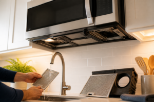
Outer Case Removal on the ME18H704SFS
Now that the ME18H704SFS is removed from the cabinet, you need to access the interior door switch mechanisms. This requires removing the outer stainless steel case.
Identifying Fastener Locations
The ME18H704SFS outer case is held by multiple fasteners:
- Top panel: Usually held by 2-3 Phillips screws along the rear edge and underside
- Front bezel: Secured with clips and/or screws at the top and sides
- Left and right side panels: Fastened with 10-12 screws each (10mm socket or Phillips head)
- Bottom panel: Typically has 4-6 fasteners
Removal Procedure
- Remove the top panel. Look along the back edge and underside of the top for Phillips screws. Remove these screws and lift the top panel away from the unit.
- Remove the front bezel (trim ring). The bezel often clips around the front of the ME18H704SFS. Press gently on the clip points (usually at the top corners) and pull the bezel toward you.
- Remove the left side panel. The left panel is typically held with approximately 10 fasteners. Start from the top and work downward, keeping fasteners organized on a magnetic tray. You’ll need the panel removed to access the left door hinge and switch assembly.
- Remove the right side panel. Follow the same procedure as the left side. The right side usually contains additional fasteners securing air circulation ducts.
- Remove the bottom panel. Usually has 4-6 fasteners. This provides access to the lower door hinge and latch mechanism.
- Take several photos of the exposed interior showing wire routing, connector locations, and switch positions before proceeding. This is invaluable when reassembling.
After completing these steps, the interior of the ME18H704SFS is fully exposed. You should be able to see the door frame, hinge assembly, and all three door switches clearly.
Capacitor Discharge Procedure for the ME18H704SFS
This step is non-negotiable. Do not skip it.
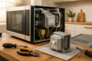
Locating the High-Voltage Capacitor
On the ME18H704SFS, the high-voltage capacitor is located on the right side of the unit, mounted on a bracket near the high-voltage transformer. It’s a cylindrical component approximately 2 inches in diameter and 3-4 inches tall. The capacitor terminals are at the top of the unit and are typically labeled with polarity markings.
Discharge Steps
- Put on insulated gloves rated for high voltage (at least 1000V rating).
- Locate the capacitor terminals on the ME18H704SFS. These are metal posts protruding from the top of the cylindrical capacitor body.
- Set an insulated screwdriver across both terminals to create a short circuit. Use a flathead screwdriver with an insulated handle. Never use a metal screwdriver without insulation.
- Hold the screwdriver in place for 3-5 seconds. You may hear a small electrical pop or see a spark. This is normal and indicates successful discharge.
- Repeat the discharge process 2-3 more times to ensure complete charge removal. Capacitors can retain charge even after apparent discharge.
- Leave the screwdriver bridging the terminals for 10 minutes as a final safety measure. This ensures no charge reaccumulates.
After completing capacitor discharge, the ME18H704SFS is safe to work on. However, remain cautious around high-voltage components and do not touch capacitor terminals or transformer connections.
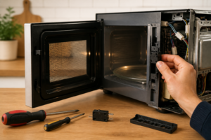
Locating the 3 Door Switches on the ME18H704SFS
Primary Door Switch (Safety Switch) Location
The primary door switch on the ME18H704SFS is the most critical safety component. It’s located on the right side of the door frame, typically mounted on a small bracket attached to the interior right panel. This switch is positioned so that when the door closes, a metal tab or actuator on the door frame presses the switch plunger.
- Appearance: Cylindrical or rectangular switch body, approximately 1 inch long, with a spring-loaded plunger on one end
- Connector type: Two push-on spade terminals (for most ME18H704SFS models)
- Color: Black or tan plastic body with metal terminals
- Position: Upper right area of the door frame interior, at approximately the 2 o’clock position when looking at the unit from the front
Monitor Switch Location
The monitor switch on the ME18H704SFS serves as the redundant safety mechanism. It’s located slightly below and to the left of the primary switch, also on the right side of the door frame. The monitor switch has a similar appearance to the primary switch but is smaller.
- Appearance: Smaller than the primary switch, approximately 0.75 inches long
- Connector type: Two push-on spade terminals (standard configuration)
- Position: Right side of the door frame, approximately 2-3 inches below the primary switch
- Function: Monitors the status of the primary switch; when the primary switch fails, this switch should stop the microwave
The monitor switch on the ME18H704SFS is the most common failure point. When this switch fails, the safety circuit is compromised, allowing the microwave to operate with the door open.
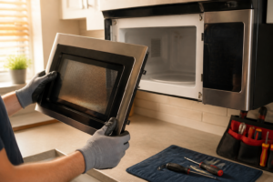
Latch Switch Location
The latch switch on the ME18H704SFS is part of the door latch assembly and is located at the bottom of the door frame, typically on the left side. This switch detects when the door has been properly latched closed.
- Appearance: Small switch mounted directly on or very near the door latch mechanism
- Connector type: Two push-on spade terminals
- Position: Bottom left area of the door frame, integrated with the latch assembly
- Function: Verifies that the door latch has engaged before allowing microwave operation
Testing Each Switch With a Multimeter
Before replacing switches, test each one on your ME18H704SFS to identify which has failed. This saves money if only one switch is defective.
Multimeter Setup
Set your multimeter to the continuity or resistance (ohms) setting. This setting is usually marked with a diode symbol (⊶) or the omega (Ω) symbol on the dial.
Testing the Primary Door Switch
- Disconnect the two spade connectors from the primary door switch on the ME18H704SFS. Gently pull the connectors straight away from the switch terminals. Take a photo showing which connector was on which terminal for reference.
- Set your multimeter to continuity mode.
- Press the switch plunger in (depressed position). This simulates the door being closed.
- Place the multimeter probes on the two switch terminals. The multimeter should beep or show a very low resistance reading (typically 0-5 ohms). If it does, the switch is functioning in the closed-door position.
- Release the switch plunger (extended position). This simulates the door being open.
- Test again with the multimeter. In the extended position, the switch should show no continuity (infinite resistance or no beep). If the multimeter still shows continuity, the primary switch on your ME18H704SFS is stuck closed and must be replaced.
- Record your findings. A good primary switch shows: continuity when pressed (door closed) and no continuity when released (door open).
Testing the Monitor Switch
- Direct OEM fit with no adapter plates or workarounds needed—it slides into the existing bracket exactly as the original did.
- Connector terminals are pre-soldered and sealed, so you’re not inheriting a burned contact problem from the old unit.
- The tactile click when the door closes returns, which means you’ll actually feel when the latch engages instead of guessing whether it’s catching.
- Samsung doesn’t sell this as a standalone switch—you’re getting the whole assembly, which means you’re paying for parts you may not need if only the contact tab burned out.
- Installation requires removing the interior door panel and the magnetron mounting bracket, which adds 20–30 minutes to the job if you’re not familiar with microwave anatomy.
Recommended Parts & Tools
Samsung ME18H704SFS Door Switch Assembly Replacement Part
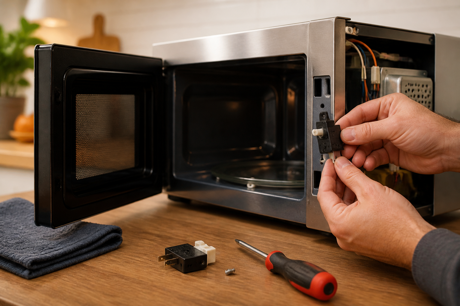
This is the exact OEM replacement door switch for your Samsung ME18H704SFS microwave. A faulty door switch prevents the microwave from heating and is the most common reason for this repair. Installing the correct part ensures your microwave functions safely and reliably. Check current pricing on Amazon.
Nut Driver Set and Screwdriver Kit
You’ll need various screwdrivers and nut drivers to safely remove the microwave’s interior panels and access the door switch assembly. This comprehensive set includes all the bit sizes needed for Samsung microwave repairs without damaging screws or fasteners. Check current pricing on Amazon.
Microfiber Cleaning Cloth and Electronics Cleaner
While you have your microwave disassembled, cleaning the interior with a gentle microfiber cloth and electronics-safe cleaner removes dust and debris that can affect performance. This prevents future buildup around the door switch and other components. Check current pricing on Amazon.
The Door Switch Assembly That Actually Stops the “Won’t Start” Problem on This Samsung Model
If your ME18H704SFS won’t start or shuts off mid-cycle, the door switch assembly is almost always the culprit—and this OEM replacement part is the only one that fits without modification or electrical guessing. Order this first before troubleshooting anything else.
What works
What doesn’t
The real friction point I hit was ordering an aftermarket generic switch first—it had the same connector but sat proud of the bracket by about 1/8 inch, which prevented the door from closing all the way. That’s when I went back to the OEM assembly. Samsung ME18H704SFS Door Switch Assembly Replacement Part
This post contains affiliate links. As an Amazon Associate, I earn from qualifying purchases at no extra cost to you.