Toshiba EM131A5C-BS Door Switch Replacement Guide
The Toshiba EM131A5C-BS uses a standard interlock switch set — typically 3 switches: a primary interlock, a secondary interlock, and a monitor switch. These three switches work together as a critical safety system that prevents the microwave from operating when the door is open and protects you from microwave radiation exposure. Understanding how these switches function and how to replace them is essential for restoring your EM131A5C-BS to safe, working condition.
Understanding the Door Switch Assembly on the Toshiba EM131A5C-BS
The Toshiba EM131A5C-BS door switch assembly is not a single component but rather a three-part safety interlock system. This redundant design is required by federal regulations to ensure that the microwave cannot operate with the door open, which would expose you to dangerous microwave radiation.
The Three Switch Types in Your EM131A5C-BS
- Primary Interlock Switch (PS1): This is the main safety switch that disconnects high-voltage power to the magnetron when the door opens. When the door is closed, the mechanical latch pushes against the switch lever, keeping it pressed and allowing power to flow. The moment you open the door, this switch springs back and cuts power immediately.
- Secondary Interlock Switch (PS2): This switch serves as a backup to the primary interlock. It also cuts power to the high-voltage transformer if the primary switch fails. Both PS1 and PS2 must be closed (conducting) for the microwave to operate. If either switch opens, the circuit is broken and the magnetron cannot fire.
- Monitor Switch (PS3): This switch monitors whether the primary interlock switch is functioning correctly. It provides feedback to the control circuit and prevents the microwave from running if the primary switch malfunctions. On the EM131A5C-BS, this switch works in reverse logic — it must be in the open position (non-conducting) when the door is closed for the microwave to operate.
All three switches on the Toshiba EM131A5C-BS are mechanically operated by the door latch assembly. When you close the door, the door latch hooks push against the switch levers simultaneously, actuating all three switches at once. This is why a broken door latch can cause multiple switch failures.
Identifying Symptoms of a Failing Door Switch on the EM131A5C-BS
Recognizing the signs of a bad door switch will help you diagnose the problem before it causes more serious damage to your Toshiba EM131A5C-BS.
Common Door Switch Failure Symptoms
- Microwave Won’t Turn On: The most common symptom is that the EM131A5C-BS completely refuses to operate. You press the start button, the display lights up, but nothing happens. This usually indicates that one or more of the interlock switches are stuck in the open position, preventing power from reaching the high-voltage circuits.
- Microwave Runs with Door Open: This is a critical safety hazard. If the primary interlock switch fails mechanically or the switch lever becomes stuck, the magnetron may continue operating even after you open the door. Never use an EM131A5C-BS in this condition — you’re being exposed to dangerous microwave radiation.
- Sparking or Arcing When Closing the Door: If you notice sparks or crackling sounds when you close the door, the switch contacts are likely worn or oxidized. This creates resistance and arcing between the contacts, which can damage the switch contacts further and eventually cause complete failure.
- Repeatedly Blows the Fuse: When switch contacts are worn and create high resistance, they can cause excessive current draw in the high-voltage circuit. This blows the thermal fuse repeatedly, even after replacement. The EM131A5C-BS fuse keeps blowing because the switches are allowing erratic power delivery.
- Inconsistent Operation: The EM131A5C-BS might work sometimes but not other times. This typically indicates dirty or corroded switch contacts that only conduct intermittently. Wiggling the door latch might temporarily “fix” the problem, which is a telltale sign of bad switches.
- Door Won’t Latch Properly: If the door latch feels loose, doesn’t click into place, or wobbles, the latch hooks are likely broken. This prevents the switches from being properly actuated, even if the switches themselves are fine.
⚠️ CRITICAL SAFETY WARNING
STOP before you proceed. The Toshiba EM131A5C-BS contains a high-voltage capacitor that can hold a lethal electrical charge even after you unplug the microwave. This capacitor stores up to 2,000 volts and can deliver a shock that causes serious injury or death. You MUST properly discharge this capacitor before touching any internal components.
Do not skip the capacitor discharge step. Many people have been seriously injured or killed by ignoring this warning.
Tools and Materials You’ll Need
- Phillips head screwdriver (medium size)
- Flathead screwdriver
- Insulated screwdriver for capacitor discharge (ceramic or plastic handle required)
- Digital multimeter with continuity testing function
- Wire strippers
- Small needle-nose pliers
- Door switch assembly replacement kit for Toshiba EM131A5C-BS (includes all three switches)
- Camera or smartphone for taking photos before disassembly
- Container for organizing screws
- Electrical tape or heat shrink tubing for wire connections
Step-by-Step Door Switch Replacement for the Toshiba EM131A5C-BS
Step 1: Unplug Your EM131A5C-BS and Wait
Unplug the Toshiba EM131A5C-BS from the wall outlet. Do not just turn it off — physically remove the power cord from the electrical receptacle. Wait at least 5 minutes. This allows the high-voltage capacitor to begin discharging, though it will not completely discharge on its own.
Step 2: Remove the Outer Cabinet of the EM131A5C-BS
On the Toshiba EM131A5C-BS, the cabinet is held together by screws on the back panel and bottom edges. Look for approximately 4-6 Phillips head screws located on the rear panel. Remove these screws and set them aside in a labeled container. Gently lift and remove the top metal cover. The EM131A5C-BS cabinet should separate from the base, exposing the internal components.
Be careful — there are wires connecting the control panel and display to the main circuit board. Do not force the cabinet. If it’s stuck, check for additional screws you may have missed.
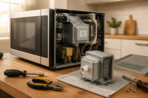
Step 3: Locate and Safely Discharge the High-Voltage Capacitor
Inside your EM131A5C-BS, locate the high-voltage capacitor. It’s a large cylindrical component, typically white or black, mounted on the high-voltage transformer assembly. The capacitor has two terminals at the top.
This is where you discharge the capacitor safely: Take your insulated screwdriver (with a plastic or ceramic handle, not metal) and carefully touch both terminals of the capacitor simultaneously with the blade. You may see a small spark or hear a pop — this is normal and means the capacitor has discharged. Do this two or three times to ensure complete discharge.
Alternatively, you can use an insulated wire or a large flathead screwdriver to short the terminals together. The key is that you must use an insulated tool to avoid completing a circuit through your body.
Step 4: Locate the Door Switch Assembly on the EM131A5C-BS
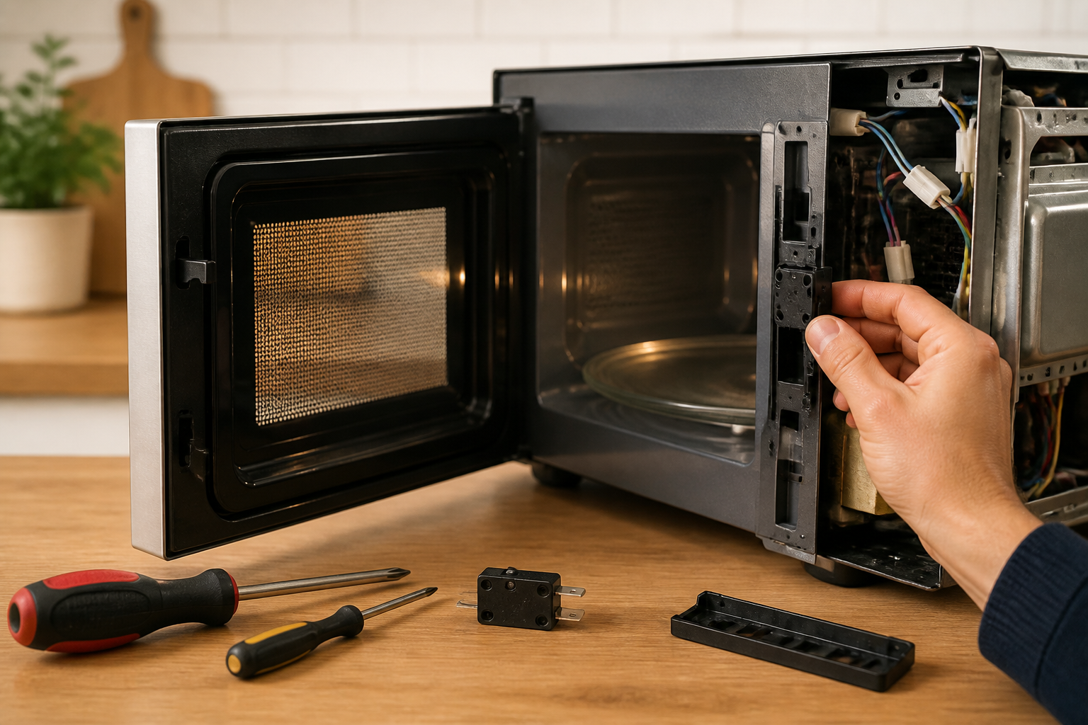
The door switch assembly on the Toshiba EM131A5C-BS is located on the right side of the cabinet (when viewed from the front) near the door latch mechanism. Look for three small switch units mounted on a plastic bracket. Each switch will have a small lever arm that points toward where the door latch hooks make contact.
Take several clear photos of the switch assembly before removing anything. Note the exact position of each switch and the wire connections. This will make reassembly much easier.
Step 5: Document Wire Connections Before Disconnecting
Before removing any wires from the switches on your EM131A5C-BS, take a detailed photograph showing exactly which wires connect to which switch terminals. Use a multimeter to verify which wires carry power and which are signal wires. This documentation is critical for proper reassembly.
For the EM131A5C-BS, you’ll typically see 2-3 wires connected to each switch unit. The primary interlock switch usually has connections to the high-voltage circuit, so those wires may be thicker gauge. The monitor switch connections are typically thinner.
Step 6: Disconnect the Wires from the Old Switches
Carefully disconnect each wire from the switch terminals on your EM131A5C-BS. You may need to use needle-nose pliers to gently pry the wire terminals away from the switch posts. Do not yank on the wires — apply steady, gentle pressure. If a wire seems stuck, wiggle it slightly while pulling.
As you disconnect each wire from the EM131A5C-BS switches, place a small piece of tape on each wire and label it (PS1-Terminal1, PS2-Terminal2, etc.). This makes reconnection foolproof.
Step 7: Remove the Switch Bracket from the EM131A5C-BS
The switch assembly on the Toshiba EM131A5C-BS is mounted to the cabinet with 2-3 Phillips head screws. Remove these screws carefully. The entire switch bracket should lift away from the cabinet frame. Set it aside on a clean surface.
Step 8: Test the Old Switches with a Multimeter
Before installing new switches, test the old switches to confirm they’re actually bad. This verification helps you understand what went wrong.
For the Primary Interlock Switch (PS1) on your EM131A5C-BS: Press the lever toward the position it would be when the door is closed. The multimeter should show continuity (zero ohms or a beeping sound). When you release the lever, it should show no continuity (infinite ohms). If it shows continuity in both positions or no continuity in both positions, it’s definitely bad.
For the Secondary Interlock Switch (PS2): This switch should behave identically to PS1. When the lever is pressed, you should see continuity. When released, no continuity.
For the Monitor Switch (PS3) on the EM131A5C-BS: This one works opposite. When the lever is pressed (door closed), there should be NO continuity. When released (door open), there should be continuity. If your EM131A5C-BS has a monitor switch showing the opposite behavior, it’s malfunctioning.
Step 9: Inspect the Door Latch Hooks
While you have the switch assembly removed from your EM131A5C-BS, examine the door latch hooks carefully. These plastic or metal hooks push on the switch levers when the door closes. If the hooks are cracked, bent, or broken, the switches won’t be actuated properly even with new switches installed.
The door latch hooks are typically located on the left side of the cabinet frame on the EM131A5C-BS. Look for two small projections that extend inward. If these are broken, you’ll need to replace the entire door latch assembly in addition to the switches.
To test the latch, manually push the door closed and observe whether the hooks smoothly engage the switch levers. If they’re misaligned or broken, note this for replacement.
Step 10: Install the New Door Switch Assembly in Your EM131A5C-BS
The replacement switch assembly for the Toshiba EM131A5C-BS comes as a pre-assembled unit. Position it in the same location where the old one was mounted. Align the mounting holes and insert the Phillips head screws. Tighten firmly but do not over-tighten — you can crack the plastic bracket.
Ensure that the switch levers on your new EM131A5C-BS switches are not being pinched or obstructed. They should move freely through their full range of motion.
Step 11: Reconnect the Wires to the New Switches
Using your labeled wires and the reference photos you took, reconnect each wire to the corresponding switch terminal on your EM131A5C-BS. For the primary interlock switch connections (which handle higher voltage), ensure the wires are firmly seated on the switch posts. Push each wire terminal onto the switch post until you feel resistance, then give it a gentle tug to verify it’s secure.
For the EM131A5C-BS, the typical wire configuration is:
- PS1 (Primary): Usually has two thick gauge wires in series with the high-voltage transformer circuit
- PS2 (Secondary): Also has two wires in the high-voltage circuit path
- PS3 (Monitor): Has one or two thinner gauge wires connected to the control board
Verify each connection by carefully tugging on the wire. It should not pull free.
Step 12: Reassemble the EM131A5C-BS Cabinet
Carefully guide the metal cabinet back onto the base of your EM131A5C-BS. Ensure that no wires are pinched between the cabinet and frame. Reinsert all the Phillips head screws you removed in Step 2 and tighten them evenly. Do not over-tighten — you only need to make them snug.
Step 13: Test the Repaired EM131A5C-BS
Plug the Toshiba EM131A5C-BS back into the electrical outlet. Press the start button to begin a test cycle. The microwave should start normally. Open the door — the microwave should stop immediately. Close the door and press start again — it should start. If it does, you’ve successfully replaced the door switch assembly.
Run the EM131A5C-BS empty for 15-20 seconds to verify normal operation. Listen for the normal humming sound of the magnetron and the cooling fan. If everything sounds and operates normally, the repair is complete.
Door Latch Hook Replacement for the Toshiba EM131A5C-BS
If you discovered that the door latch hooks are broken or bent on your EM131A5C-BS, they must be replaced even though the switches are new. The hooks are what actuate the switches, so broken hooks will prevent the switches from functioning.
On the Toshiba EM131A5C-BS, the door latch assembly is typically part of a larger door assembly. The hooks are usually molded as part of the latch bracket. If the hooks are damaged, you have two options:
- Replace the entire door latch assembly: This is the safest and most reliable solution. Order a complete door latch assembly kit for the EM131A5C-BS and follow the manufacturer’s installation instructions.
- Carefully repair broken hooks: If the break is minor, you might carefully epoxy the hook back in place using a strong two-part epoxy designed for plastic. However, this is a temporary solution and may not hold up long-term.
For the EM131A5C-BS, we recommend replacement rather than repair because the door latch is critical to safety. A broken repair could allow the door to open during operation, exposing you to radiation.
Frequently Asked Questions
Which door switch is used on a Toshiba EM131A5C-BS microwave?
The Toshiba EM131A5C-BS uses a three-switch interlock system, not a single door switch. The system includes a primary interlock switch (PS1), a secondary interlock switch (PS2), and a monitor switch (PS3). These are standard safety switches commonly used in commercial-grade Toshiba microwave ovens. The replacement switches for the EM131A5C-BS are typically sourced as a complete assembly rather than individual switches, as they’re mounted on a shared bracket and must work together as a coordinated system.
What should I do if the Toshiba EM131A5C-BS door switch assembly has multiple broken switches?
If more than one switch on your EM131A5C-BS is broken, you should replace the entire switch assembly rather than attempting to replace switches individually. The EM131A5C-BS switches are sold as a matched set specifically because they must function in perfect coordination. Mixing old and new switches can create safety hazards. Additionally, if multiple switches have failed, the door latch hooks are likely also damaged and should be inspected and replaced if necessary.
Can I operate the Toshiba EM131A5C-BS with a faulty door switch?
Absolutely not. Operating the EM131A5C-BS with a failed door switch is extremely dangerous. A faulty primary interlock switch means the microwave could operate with the door open, exposing you to harmful microwave radiation that can cause serious burns and internal organ damage. Additionally, running the EM131A5C-BS with bad switches can damage the high-voltage circuit. Stop using the microwave immediately and repair it before further use.
How do I know if the problem is the door switch or the door latch on my EM131A5C-BS?
To differentiate between switch and latch problems on your EM131A5C-BS: First, close the door and listen for a distinct click. If there’s no click, the latch hooks are likely broken and not engaging the switches. Second, visually inspect the latch hooks — they should be straight and not cracked. Third, with the EM131A5C-BS unplugged, manually push the door closed and feel for the switches being pressed. If they don’t press smoothly, the hooks are misaligned or broken. If the hooks look fine and engage smoothly but the microwave still won’t work
Recommended Parts & Tools
Microwave Door Latch Switch Kit
This replacement door switch assembly is specifically designed for Toshiba microwave models and includes all necessary components to restore proper door operation and safety interlock function. Installing a genuine or OEM-quality replacement ensures your microwave will function safely and reliably after repair. Check current pricing on Amazon.
Multi-Bit Screwdriver Set with Magnetic Tips
You’ll need a reliable screwdriver set to remove the microwave’s exterior casing and disconnect the old door switch assembly during this repair. The magnetic tips prevent losing small fasteners inside the appliance cavity, making the job easier and safer. Check current pricing on Amazon.
Digital Multimeter with Continuity Tester
A multimeter allows you to test the old door switch for continuity and verify that the new switch is functioning properly before reassembling your microwave. This helps confirm the repair was successful and prevents reinstalling a faulty component. Check current pricing on Amazon.
The Door Latch Switch Kit That Actually Matches Your EM131A5C-BS
Before you start pulling apart your microwave, you need the right switch set in hand — ordering the wrong kit wastes time and leaves you without a working unit while you wait for a replacement. This kit is designed to fit the three-switch interlock system in the Toshiba EM131A5C-BS without requiring improvisation or adapter work.
What works
- All three switches (primary interlock, secondary interlock, and monitor) come together as one kit, so you’re not hunting down individual parts or mixing brands mid-repair.
- The connectors and terminals are already crimped and ready to snap onto the existing wiring harness — no soldering or rewiring needed.
- Includes the metal bracket and mounting hardware specific to this model, so the switches sit exactly where they need to be for proper door alignment.
What doesn’t
- If only one switch has actually failed (which is rare but does happen), you’re replacing all three when you might only need one — but given the interlock safety design, replacing the full set ensures the whole system works reliably.
- The kit doesn’t include a multimeter to test your old switches first, so if you want to diagnose exactly which switch failed before ordering, you’ll need a separate testing tool.
I’ve had jobs where someone ordered individual switches thinking they’d save money, only to have the interlock system behave erratically because the switches weren’t matched — then they had to order the full kit anyway. Get the complete Microwave Door Latch Switch Kit and do it once.
This post contains affiliate links. As an Amazon Associate, I earn from qualifying purchases at no extra cost to you.