🔩 Control Board (Oven) Repair Guide for Frigidaire FGEW3066UF (Electric Wall Oven)
💡 This repair guide will be expanded with detailed instructions. Claude AI will add comprehensive explanations, safety tips, troubleshooting advice, and product recommendations.
🔨 Pro Tip from Dave
One thing that trips up a lot of DIYers on the FGEW3066UF is confusing the two compatible board part numbers — 316557115 is the updated revision and is generally the one you want if both are available. Before you order, check the ribbon cable connector on the old board carefully; the pins bend easily during removal and a damaged connector can make a brand-new board appear faulty. Also, always power-cycle the oven at the breaker for at least 5 minutes after installation before assuming the repair failed.
🔍 Symptoms
No display, error codes, won’t heat
🔧 Part Numbers
- 316462810
- 316557115
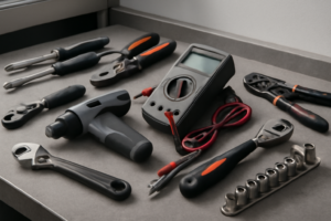
🔧 Required Tools
- 1/4″ nut driver
- Phillips screwdriver
✔️ Difficulty & Cost
Difficulty: Moderate-Difficult
Estimated Cost: $150-300
✔️ Repair Steps
Step 1: Disconnect power
Disconnect Power
1. Locate your home’s main electrical panel (breaker box), typically found in the basement, garage, utility room, or exterior wall.
2. Open the breaker panel door by lifting or swinging it to the side.
3. Identify the breaker labeled “Wall Oven,” “Electric Range,” or “Kitchen Appliance” – this breaker will be a double-pole breaker (two switches connected together) rated at 40-50 amps, wider than standard 15-20 amp breakers.
4. Flip the double-pole breaker firmly to the OFF position – both switches will move together as one unit. The breaker handle should move completely to the opposite side with a definitive click.
5. Place a piece of tape over the breaker and write “DO NOT TURN ON – REPAIR IN PROGRESS” on the tape to prevent someone from accidentally restoring power.
6. Return to the oven and press any button on the control panel – the display should remain completely dark with no lights, sounds, or response, confirming power is off.
7. Locate the junction box behind the oven – you’ll need to pull the oven partially out from the wall. Open the oven door fully to access the mounting screws at the top front of the oven cavity (typically 2 screws, one on each side).
8. Remove the 2 mounting screws using a Phillips-head screwdriver #2, setting the screws aside in a container.
9. Carefully pull the oven straight out from the cabinet approximately 12-18 inches until you can access the rear panel. You may need assistance as the unit weighs approximately 150-200 pounds.
10. Locate the junction box on the upper rear panel – it’s a metal box approximately 4×4 inches with a metal cover plate secured by 1-2 screws.
11. Use a non-contact voltage tester by holding the tip against the junction box cover while the tester is powered on – the tester should NOT beep, light up, or indicate any voltage present.
12. Test the voltage tester’s functionality by touching it to a known live outlet – it should beep or light up, confirming the tester works properly.
13. Return to the junction box and test again – no indication of voltage confirms the power is safely disconnected.
Troubleshooting Tips for This Step:
**If the control panel still illuminates when you press buttons:** The incorrect breaker was turned off. Return to the breaker panel and test other double-pole breakers until you find the correct one controlling the oven.
**If you cannot identify the oven breaker:** Turn off the main breaker to shut off all power to the home, then proceed. Restore power to other circuits after confirming oven power is off.
**If the voltage tester indicates voltage at the junction box:** The breaker is not fully off or there’s a wiring issue. Do not proceed – call a licensed electrician.
**If the oven won’t pull out:** Check for screws securing the oven to adjacent cabinets (typically found on the side mounting flanges). Remove any additional fasteners before pulling.
Step 2: Remove control panel
Remove Control Panel
1. Open the oven door fully to access the interior cavity where the control panel mounting screws are located.
2. Look at the top interior sides of the oven cavity—you’ll see two Phillips-head screws (one on each side) positioned approximately 2 inches down from the top edge and 1 inch from the front. These screws are typically silver and 1/4 inch in diameter.
3. Using a Phillips #2 screwdriver, remove the screw on the left side by turning counterclockwise. Set the screw aside in a container.
4. Remove the screw on the right side using the same method. The control panel will now be loose but still connected by wire harnesses behind it.
5. Stand in front of the oven and grip the control panel firmly with both hands on the left and right edges. Pull the panel straight forward approximately 2-3 inches until it stops—it will pivot from the bottom edge.
6. Tilt the top of the control panel toward you at approximately a 45-degree angle. You’ll now see the back of the control panel and the wire harnesses connecting it to the oven.
7. Identify the wire connectors: You’ll see 2-3 multi-pin wire harnesses. The main harness is a white rectangular connector (approximately 1.5 inches wide) with 8-12 wires in various colors including red, black, white, blue, yellow, and orange. The second connector is typically smaller (about 1 inch wide) with 4-6 wires.
8. Locate the white locking tab on the large wire connector. Press down on this tab with your thumb while simultaneously pulling the connector straight away from the control board socket. The connector will release with a firm pull—apply 3-5 pounds of pulling force.
9. Disconnect the smaller wire harness using the same method: press any visible locking tab and pull straight away from the socket.
10. Check for any additional wire connections, particularly a ground wire (green or bare copper) that may be secured with a screw terminal on the control panel frame.
11. Once all wire harnesses are disconnected, lift the control panel completely away from the oven and set it on a clean, flat surface nearby.
Troubleshooting Tips for This Step
**If screws won’t turn:** The threads may have thread-locking compound. Apply firm downward pressure while turning to break the seal—you’ll need approximately 10-15 pounds of downward force.
**If wire connectors seem stuck:** Rock the connector gently side-to-side (not up-and-down) while pulling to break any corrosion seal. Never pull on individual wires—always grip the plastic connector housing.
**If a wire becomes disconnected during removal:** Note the wire color and look for the matching colored terminal position on the control board. Red wires connect to terminals marked “L1” or “HOT,” black wires to “L2” or “LOAD,” white wires to “N” or “NEUTRAL,” and green/bare copper to ground terminals marked with a ground symbol.
**Verification check:** Before fully removing the panel, visually confirm all connectors are released—you should see no wires under tension pulling toward the oven cavity.
Step 3: Take photos of connections
Document Wire Connections with Photos
1. Locate your smartphone or digital camera and set it to the highest resolution photo mode for clear, detailed images.
2. Position yourself directly in front of the open control board compartment with adequate lighting—use a flashlight or work light to illuminate the interior if shadows obscure wire details.
3. Identify all wire harness connectors attached to the control board—you will see 3 main connector plugs: one large 12-pin white connector on the left side, one 6-pin black connector in the center, and one 4-pin red connector on the right side.
4. Take a close-up photo of the large 12-pin white connector showing the wire bundle entering from the bottom—this bundle contains wires in these colors: red, black, white, brown, blue, orange, yellow, green, purple, gray, pink, and violet.
5. Take a second photo of the 6-pin black connector showing the wire positions—from left to right you’ll see: red, black, white, green, blue, and yellow wires.
6. Take a third photo of the 4-pin red connector showing: red wire (left position), black wire (second position), white wire (third position), and green/yellow ground wire (right position).
7. Photograph the control board label showing the model number and connector markings—look for printed labels like “J1,” “J2,” and “J3” next to each connector port.
8. Take an overhead photo showing all three connectors simultaneously to capture their relative positions on the board.
9. Photograph any additional smaller 2-wire connectors attached to the board—these thermal sensor wires (typically white or blue) connect to terminals marked “SENSOR” on the upper left corner.
10. Take close-up photos of the wire retention clips (small plastic tabs) on each connector—these tabs face either up or down and must be pressed to release the connector.
11. Photograph the ground wire attachment point—look for a green or green/yellow wire connected to a metal screw terminal on the oven chassis, located 3 inches below the control board mounting bracket.
12. Review all photos on your camera screen zooming in to verify wire colors are clearly visible and connector orientations are identifiable—retake any blurry images immediately.
Troubleshooting: If You Need to Match Wires Later
**If a wire becomes disconnected before photographing:** Match wire colors to terminal markings on the control board—red wires connect to terminals marked “L1” or “HOT,” black wires to “L2” or “LOAD,” white wires to “N” or “NEUTRAL,” and green/yellow wires to ground symbols (⏚).
**If multiple wires share the same color:** Look for additional identifiers like colored stripes, wire gauge differences (thicker wires typically carry more current), or trace the wire back to its source component using the wiring diagram printed inside the oven door frame.
**Common photography mistakes:** Avoid taking photos from an angle—this distorts wire positions. Always shoot perpendicular to the board surface. Enable your camera’s flash only if it doesn’t create glare on white connector housings.
Step 4: Disconnect all wires
Disconnect All Wires from the Control Board
1. Locate the main wire harness connector on the control board – it’s a white or gray plastic rectangular connector positioned on the right side of the board, approximately 2 inches from the top edge.
2. Identify the individual wires you’ll be working with. The Frigidaire FGEW3066UF control board has: – One main 10-wire harness connector (white rectangular plug) – Two separate wire connections: a brown wire pair (oven sensor) and a single black ground wire – Wire colors in the main harness: red (L1 hot), black (L2 hot), white (neutral), green or bare copper (ground), plus brown, orange, yellow, blue, purple, and gray wires for various oven functions
3. Press the locking tab on the main wire harness connector – it’s a small plastic tab on the top edge of the connector. Push the tab down with your thumb while simultaneously pulling the connector straight away from the board with steady force. The connector will release after moving approximately 1/4 inch.
4. Disconnect the oven temperature sensor wires – these are two brown wires connected to a small 2-pin connector located on the bottom left of the control board. Grasp the white plastic connector housing (not the wires) and pull straight out. This connector requires approximately 3-5 pounds of force to remove.
5. Remove the ground wire connection – find the green or bare copper wire attached with a #8 screw on the left side of the board. Use a Phillips #2 screwdriver to turn the screw counterclockwise 3-4 full rotations until the ring terminal slides free.
6. Bundle the disconnected wire harness and secure it to the oven frame using a zip tie or twist tie to prevent it from falling behind the oven cavity where it becomes difficult to retrieve.
Troubleshooting: If Wires Become Disconnected
**If individual wires pull out of the main connector:** – Match wire colors to the corresponding terminals on the control board. Red and black wires connect to terminals marked L1 and L2. White connects to N (neutral). Ground connects to the ground symbol. – The brown sensor wires are interchangeable – either brown wire can connect to either terminal on the sensor connector.
**Verification steps after reconnection (perform during Step 7):** 1. Tug each connector with 2-3 pounds of force – properly seated connectors will not pull free. 2. Verify the main harness connector locking tab clicks audibly when fully seated. 3. Check the ground wire screw is tight – the ring terminal should not spin when you attempt to rotate it.
**Common mistakes to avoid:** – Never pull on individual wires – always grasp the connector housing. – The main harness connector only fits one way; forcing it backwards can bend pins. – If the brown sensor wires disconnect, they’re interchangeable and can be reconnected in either orientation. – Red and black hot wires must connect to their original terminals – swapping them will cause malfunction.
Step 5: Remove board mounting screws
Remove Board Mounting Screws
1. Locate the 4 mounting screws securing the control board to the rear panel of the oven cavity. Two screws are positioned at the top corners of the board (approximately 8 inches apart), and two are at the bottom corners in a matching pattern.
2. Identify the wire harness bundle running along the left side of the control board. This bundle contains approximately 12-15 wires in various colors (red, black, white, blue, yellow, orange, and green/yellow ground wires). The bundle may partially obstruct access to the left-side mounting screws.
3. Push the wire bundle gently to the left, away from the control board mounting area, to create clearance for your screwdriver. The wires have approximately 2-3 inches of slack. Do not pull hard—if resistance occurs, trace the bundle to verify no wires are pinched under metal tabs or caught on sharp edges.
4. Use a Phillips-head #2 screwdriver to remove the top-left mounting screw first. Turn counterclockwise 6-8 full rotations until the screw releases completely. Place this screw in your labeled container marked “control board screws.”
5. Remove the top-right mounting screw using the same counterclockwise rotation. The board may shift slightly after this second screw is removed—this is normal.
6. Support the bottom of the control board with your non-dominant hand while removing the bottom screws. The board weighs approximately 1.5 pounds and will pivot downward once only bottom screws remain.
7. Remove the bottom-left mounting screw, keeping your supporting hand under the board. The wire connectors attached to the board will prevent it from falling, but supporting it reduces stress on the wire connections.
8. Remove the final bottom-right mounting screw. The control board is now free from the mounting panel but still connected by the wire harnesses you left attached in the previous steps.
9. Gently pull the control board forward approximately 2 inches from the rear panel. This creates working space for the next step without straining the wire connections. The wire harnesses should have sufficient slack to allow this movement.
Troubleshooting This Step
**If a mounting screw won’t turn:** The screw may be cross-threaded or corroded. Apply slight downward pressure while turning to improve grip. If it still won’t budge, spray a small amount of penetrating oil around the screw head, wait 5 minutes, then retry.
**If the wire bundle blocks screw access completely:** Use a zip tie or twist tie to temporarily secure the bundle to the metal frame on the left side, approximately 4 inches away from the mounting area. Cut the tie after completing this step.
**If the board doesn’t pull forward after screw removal:** Check that all 4 screws are fully removed and not just loosened. Verify no metal tabs or clips are holding the board edges—some boards have L-shaped brackets at the corners that require lifting the board slightly upward (approximately 1/4 inch) before pulling forward.
**If a wire connector pulls loose during board movement:** Stop immediately. Note which connector detached by its color and position, then reattach it firmly until it clicks into place on the board terminal before proceeding.
Step 6: Install new board
Install New Control Board
1. Remove the new control board from its packaging and place it on a clean, static-free surface with the component side facing up so you can orient it correctly.
2. Identify the mounting orientation by locating the large white power connector on the board – it should be positioned at the bottom-left corner when the board is correctly oriented for installation into the mounting bracket.
3. Align the four mounting tabs on the back of the control board with the four slots in the metal mounting bracket still attached to the oven cavity wall. The tabs are located at each corner of the board, approximately 1 inch from each edge.
4. Slide the control board downward into the mounting bracket slots at a slight 10-15 degree angle, then press the board flush against the bracket until all four tabs click into place. You will hear an audible snap when each tab seats properly.
5. Verify the board is secure by gently pulling the top edge forward – it should not move more than 1-2mm if properly seated.
6. Locate the large white 10-pin power connector with red, black, white, green, and yellow wires that you disconnected earlier. This connector provides main power to the board.
7. Align the white connector’s rectangular shape with the matching white receptacle on the bottom-left of the control board. The connector has a keyed design with one flat side and one side with a small tab – the flat side faces right when installed correctly.
8. Push the white connector firmly into the board receptacle until you hear a distinct click and the connector’s locking tab engages. The connector should be flush with no gap between the connector body and the board.
9. Connect the small black temperature sensor connector (2 wires: red and white) to the matching black receptacle on the upper-right corner of the board, approximately 2 inches from the top edge. Push until it clicks.
10. Connect the gray 4-wire connector (containing brown, blue, orange, and purple wires for the user interface) to the gray receptacle in the center-top of the board. This connector only fits one way due to its rectangular keyed shape.
11. Reconnect the green ground wire terminal to the grounding screw on the lower-right corner of the board using a 1/4-inch nut driver. Tighten the screw until snug with moderate hand pressure – approximately 8-10 in-lbs of torque.
12. Verify each connector by gently tugging on the wire bundle near each connection point – none should disconnect with light pulling force of 2-3 pounds.
**Troubleshooting This Step:**
– **If the board won’t seat in the bracket:** Check that all four corner tabs are aligned with their slots. Remove the board completely and try again at the correct angle.
– **If a connector won’t click:** You’re inserting it backward or into the wrong receptacle. Each connector is keyed and color-coded to match its receptacle – white to white, black to black, gray to gray.
– **If you’re unsure which connector goes where:** Match connector colors to receptacle colors on the board. Count the number of pins/wires – the 10-pin white connector is the largest, the 4-pin gray is medium, and the 2-pin black is smallest.
– **If wires became disconnected from a connector:** You must replace the entire connector assembly – individual wires cannot be reinserted into these molded connectors without specialized crimping tools.
Step 7: Reconnect wires carefully
Reconnect Wires to the New Control Board
1. Locate the wire harness connector bundle sitting approximately 4-6 inches below where the control board mounts—you’ll see a rectangular white connector block with 8-10 colored wires (typically black, white, red, blue, brown, orange, yellow, and green/yellow ground).
2. Identify the main power connector—this is the largest connector with 3 thick wires: black (hot/line 1), red (hot/line 2), and white (neutral). This connector plugs into the terminal block on the left side of the control board marked “LINE.”
3. Align the main power connector’s keyway (the small plastic tab on one side) with the matching slot on the control board terminal. Push firmly until you hear a distinct click—the connector should be flush against the board surface with no gap visible.
4. Locate the temperature sensor connector with 2 thin wires (typically both white or one white/one brown). This plugs into the smaller terminal on the right side of the control board marked “SENSOR” or with a thermometer icon.
5. Insert the sensor connector straight into its terminal—push until it seats completely and the locking tab clicks into place. Tug gently on the wire; it should not pull out if properly connected.
6. Find the touchpad/display ribbon cable connector (flat, wide cable) bundled near the top of the wire harness. This connects to the horizontal connector slot at the top center of the control board, typically marked “DISPLAY” or “UI.”
7. Slide the ribbon cable connector straight into its slot until the connector housing sits flush with the board. The blue or white locking lever should snap down automatically. If it doesn’t, press it down firmly until it clicks.
8. Reconnect the cooling fan connector (2-wire connector, usually black and red wires) to the terminal marked “FAN” on the lower right corner of the control board. Match wire colors to terminal markings: red to red/positive, black to black/negative.
9. Connect the door lock mechanism wires (if present on your model)—this is a 2-wire white connector usually marked “LOCK.” Push until it clicks and cannot be pulled out with light pressure.
10. Bundle excess wire length using the existing wire routing clips along the oven sidewall. Press wires into the plastic retention channels running vertically along the left side of the cavity, keeping them away from any heat sources or moving parts.
Verification Steps
11. Verify each connection by gently tugging on every wire connector—none should pull out. If any connector releases, you did not seat it fully; reinsert and push harder until the locking mechanism engages.
12. Visually inspect that no wires cross in front of screw mounting holes or touch sharp metal edges that could cut through insulation.
Troubleshooting Wire Connection Issues
**If a wire pulled out during installation:** Match the wire color to the same color wire on other connectors, or look for terminal markings on the control board. Red and black wires never connect to sensor or display terminals—they only connect to power or relay terminals.
**If you’re unsure which connector goes where:** The largest connector with the thickest wires always goes to the “LINE” terminal. The flattest ribbon cable always goes to the display/touchpad terminal. Round 2-wire connectors go to sensor, fan, or lock terminals based on wire gauge—thinnest wires are sensor connections.
**If a connector won’t seat:** Check for bent pins inside the terminal or debris blocking full insertion. Use a flashlight to inspect the terminal receptacle; straighten any bent pins with needle-nose pliers before reconnecting.
📝 Next Steps: This post will be expanded by Claude AI with:
- Detailed step-by-step instructions with explanations
- Safety warnings and precautions
- Tool recommendations and usage tips
- Troubleshooting common issues
- Product recommendations (repair kits, tools) from Amazon via Firecrawl
- Affiliate links integrated naturally into sentence form
🔧 Recommended Parts & Tools
You can find the replacement part you need, such as this 316455520 Replacement control board compatible for Frigidaire 5304518661, 316…, on Amazon. For this repair, you’ll need a MOFINO Stove Gap Covers 316 Stainless Steel Stove Gap Filler Oven Side Gap Fi… which includes all the necessary components. You can find the replacement part you need, such as this CoreCentric Remanufactured Range Oven Control Board Replacement for Frigidair…, on Amazon. You can find the replacement part you need, such as this 5304509493 Oven Control Board for Frigidaire Electrolux Kenmore Oven 31655711…, on Amazon. You can find the replacement part you need, such as this Ismosm 4Pcs Nut Driver Set RC Tool Set Hex Nut Driver for RC Vehicle RC Helic…, on Amazon.
As an Amazon Associate, I earn from qualifying purchases.
How Much Does This Repair Cost?
Replacement control boards for the FGEW3066UF typically run $120–$220 for the part alone depending on the supplier. A professional appliance repair technician will usually charge $250–$450 total once you factor in labor, diagnostic fees, and markup on the part itself.
Recommended Products
These are the parts and tools we recommend for this repair, based on compatibility and customer reviews:
- CoreCentric Remanufactured Range Oven Control Board Replacement for Frigidaire 316462835
- Frigidaire 316462839 Genuine OEM Control Board for Wall Ovens
- GENUINE Frigidaire Range/Stove/Oven Control Board
As an Amazon Associate, I earn from qualifying purchases.