🔩 Bake Element Replacement Repair Guide for GE JB645RKSS (Electric Range)
💡 This repair guide will be expanded with detailed instructions. Claude AI will add comprehensive explanations, safety tips, troubleshooting advice, and product recommendations.
🔨 Pro Tip from Dave
When replacing the bake element on the JB645RKSS, don’t yank the element forward too aggressively — the wire harness connectors in the back of the oven cavity are short and the insulation gets brittle with age. Use part WB44X200 as the preferred replacement; WB44X5082 is the older cross-reference. A common mistake is failing to check that both terminal connectors are fully seated and tight before powering back up, which causes arcing.
🔍 Symptoms
Oven won’t heat, uneven baking, element has holes/blisters
🔧 Part Numbers
- WB44X200
- WB44X5082
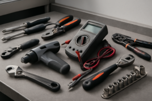
🔧 Required Tools
- Phillips screwdriver
- 1/4″ nut driver
- work gloves
✔️ Difficulty & Cost
Difficulty: Easy
Estimated Cost: $25-40
✔️ Repair Steps
Step 1: Turn off power at breaker
1. Locate your home’s main electrical panel (breaker box), typically found in the basement, garage, utility room, or on an exterior wall.
2. Open the breaker panel door by pulling the metal handle or lifting the plastic cover outward.
3. Look for the breaker labeled “Range,” “Electric Range,” “Stove,” or “Kitchen Range.” This breaker will be a double-pole breaker (two switches connected together, appearing as one wide switch) rated for 40 or 50 amps.
4. Identify the breaker position by checking if the switch handle is aligned with other breakers marked “ON” (typically pointing toward the center of the panel) or if you see an orange or red indicator showing through a small window on the breaker face.
5. Flip the range breaker to the OFF position by pushing the switch handle firmly away from the panel’s center until it clicks into place and aligns with other breakers marked “OFF.” The handle will move approximately 1/4 inch and should stay in this position without springing back.
6. Verify the breaker is off by attempting to turn on the oven using the control panel. Press the “Bake” button and try to set a temperature. The display should remain dark or show no response.
7. Return to the breaker panel and place a piece of masking tape or painter’s tape across the breaker switch and panel door edge to prevent accidental re-energization while you work.
8. Write “DO NOT TURN ON – REPAIR IN PROGRESS” on the tape using a permanent marker.
9. Test the oven control panel one final time by pressing multiple buttons including “Bake,” “Broil,” and any cooktop element controls. You should see no lights, no display illumination, and hear no beeps or clicks.
10. Open the oven door fully and visually inspect inside the oven cavity. Look at the existing bake element (the wide metal coil at the bottom of the oven). It should not be glowing red or showing any heat. Hold your hand 6 inches above the element for 5 seconds to confirm no residual heat remains.
11. Proceed to Step 2 only after confirming zero electrical response from all oven controls and no heat from the existing element.
Step 2: Remove oven racks
1. Open the oven door fully until it stops at approximately 90 degrees from the closed position.
2. Look inside the oven cavity and count the number of racks installed (the GE JB645RKSS typically comes with 2 standard oven racks, though yours may have 1, 2, or 3 depending on configuration).
3. Identify the rack slide rails on both the left and right interior oven walls—these are the horizontal metal guides with raised edges that the racks slide along.
4. Starting with the top rack, grasp it with both hands, one on each side of the front edge, positioning your hands approximately 8 inches apart.
5. Pull the rack straight toward you until it stops at the safety notch position (approximately 6-8 inches out from the fully inserted position)—you’ll feel resistance when the rack catches on these notches.
6. Lift the front edge of the rack upward by approximately 1 inch to clear the safety notches on both sides.
7. Continue pulling the rack toward you while maintaining the slight upward angle until it completely clears the slide rails and is free from the oven cavity.
8. Set the removed rack aside on a protected surface like a towel on your counter or floor to prevent scratching.
9. Repeat steps 4 through 8 for each remaining rack until the oven cavity is completely empty.
10. Look inside the now-empty oven and verify no racks, rack accessories, or loose items remain—you should see only the bare metal walls, the bake element at the bottom (a circular or straight heating coil), and the broil element at the top.
11. Inspect the empty oven floor where the bake element sits—this is the flat metal surface at the bottom of the oven cavity where the element will be removed in the following steps.
**Success Check:** The oven interior is completely empty with clear access to all four interior walls and both heating elements. You can reach your hand into the oven without obstruction and touch the bottom surface where the bake element connects through the mounting bracket holes (typically located at the center-rear of the oven floor).
Step 3: Remove two screws at rear of element
1. Locate the two mounting screws at the rear of the bake element where it attaches to the back wall of the oven cavity. These screws are positioned approximately 4-6 inches apart from each other, centered horizontally on the back wall, about 2-3 inches up from the oven floor.
2. Identify the screw type. On the GE JB645RKSS, these are hex-head screws requiring a 1/4-inch nut driver or socket. Some units may have Phillips-head screws requiring a #2 Phillips screwdriver.
3. Insert your 1/4-inch nut driver onto the right-side screw (when facing the oven). Turn counterclockwise 8-10 full rotations until the screw releases completely from the mounting bracket.
4. Pull the screw straight out and place it in a container. The screw length is approximately 3/4 inch with threads along the entire shaft.
5. Repeat the removal process on the left-side screw. Insert the nut driver, turn counterclockwise 8-10 rotations, and remove completely.
6. With both screws removed, grasp the element terminals (the flat metal prongs at the rear of the element) with one hand. Apply gentle but firm pulling pressure straight forward, moving the element approximately 1-2 inches away from the back wall.
7. The element will now pivot loosely on its terminals. The terminals remain inserted into the electrical connector receptacles in the back wall—do not pull the element completely free yet, as the terminals are still making electrical contact with the wiring.
8. Examine the mounting bracket area where the screws were removed. You’ll see two round holes in a metal bracket attached to the back wall. This bracket supports the weight of the element during normal operation.
9. Verify both screws are fully removed by looking through the mounting holes—you should see clear space with no screw threads visible.
10. The element should now move freely when pushed or pulled, pivoting on the terminal connection point. This confirms the mounting screws no longer secure the element to the back wall.
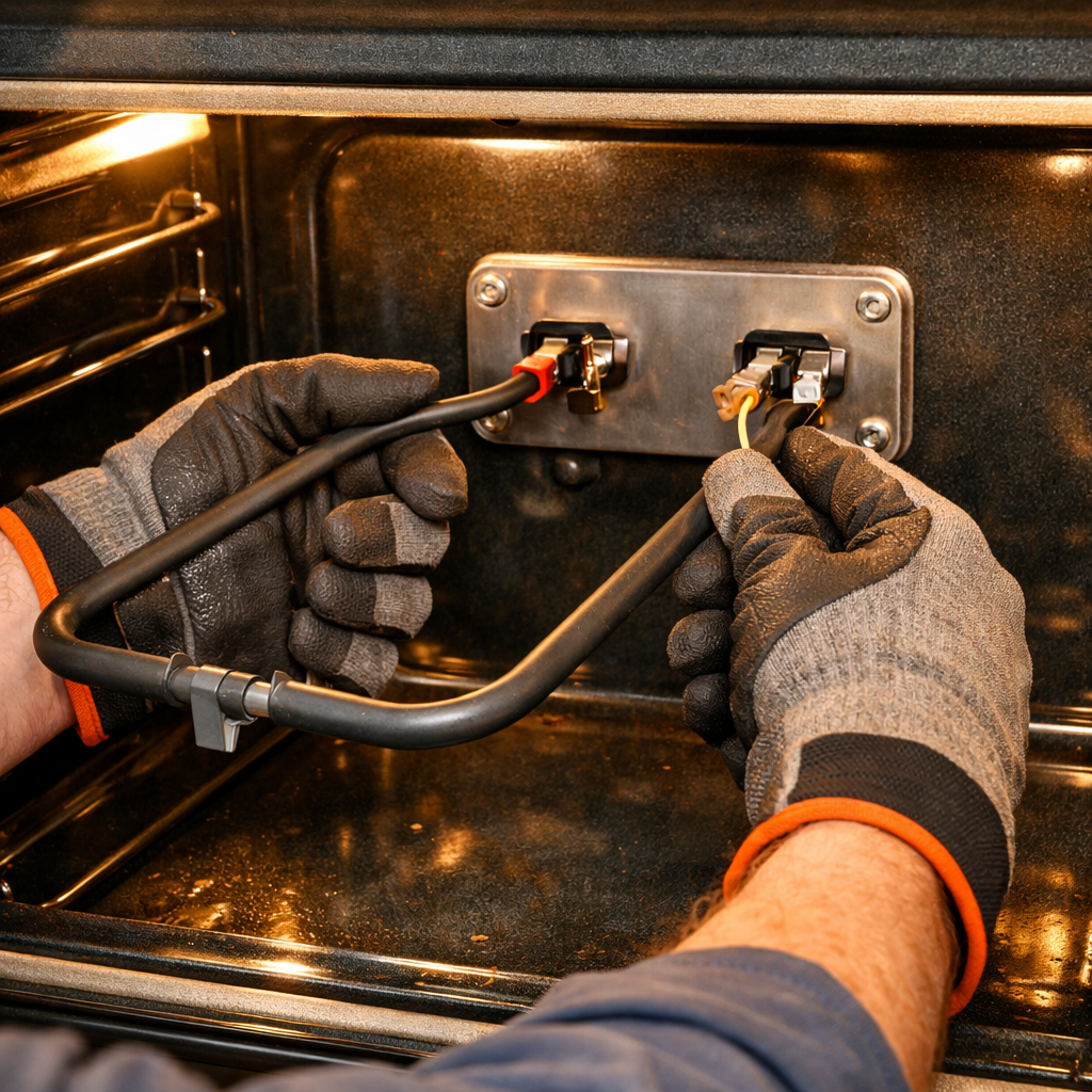
Step 4: Pull element forward, disconnect wire terminals
1. Grasp the bake element at both outer ends where the metal element meets the bracket, approximately 2 inches from each side edge of the oven cavity.
2. Pull the element straight toward you with steady pressure, moving it approximately 3-4 inches forward out of the oven cavity. The element will slide out from the two terminal receptacles mounted to the rear oven wall.
3. Continue pulling until you can see the two metal terminal prongs extending from the back of the element. These are flat blade terminals, approximately 1/4 inch wide and 1 inch long.
4. Look at the exposed terminals now visible behind the element. You’ll see two wire connections, each consisting of a wire with a female spade connector (metal sleeve) attached to each terminal prong.
5. Locate the left terminal connection first. Grip the metal spade connector (not the wire insulation) between your thumb and forefinger.
6. Pull the spade connector straight off the terminal prong using a firm, steady motion. The connector requires approximately 5-8 pounds of force to remove. Rock the connector side-to-side slightly while pulling if it resists initial removal.
7. Once the left connector is free, let the wire hang down naturally. The wire is typically 6-8 inches long and will not fall back into the wall.
8. Repeat the disconnection process with the right terminal. Grip the metal spade connector and pull straight off the terminal prong.
9. With both wires disconnected, pull the element completely out of the oven cavity. The element should now be free and separate from the range.
10. Examine the two female spade connectors you just removed. They should be clean and show no signs of burning, melting, or corrosion. Burned connectors appear blackened or have melted insulation within 1 inch of the metal connector.
11. Set the old element aside on a heat-resistant surface. The element should now be completely disconnected with both wire terminals hanging freely inside the oven cavity, ready for the new element installation.
12. Note the wire positions: both wires typically have the same color insulation (often white or gray), making position interchangeable on this model.
Step 5: Install new element in reverse order
1. Hold the new bake element by its outer metal frame and position it so the two metal terminal prongs face toward the back wall of the oven cavity.
2. Align the element’s mounting bracket holes (located on each side of the element where it meets the back wall) with the two screw holes visible on the rear oven wall, positioned 18 inches apart horizontally and 3 inches up from the oven floor.
3. Insert the element’s terminal prongs through the two rectangular openings in the rear oven wall, pushing them through until the mounting bracket sits flush against the wall surface.
4. Reach behind the oven through the access opening at the bottom rear and locate the two terminal prongs now protruding through the wall, each approximately 2 inches long and 1/4 inch wide.
5. Take the first wire connector (with one red wire and one black wire crimped together) and slide it onto the left terminal prong when facing the back of the range, pushing firmly until the metal prong is no longer visible inside the connector.
6. Slide the second wire connector (with one red wire and one black wire crimped together) onto the right terminal prong, pushing until fully seated—you will feel resistance when the connector bottoms out on the prong.
7. Insert one of the two 1/4-inch hex head screws through the left mounting bracket hole and thread it into the oven wall by hand, turning clockwise 3-4 complete rotations until finger-tight.
8. Insert the second 1/4-inch hex head screw through the right mounting bracket hole and thread it clockwise by hand until finger-tight.
9. Using a 1/4-inch nut driver, tighten the left screw by turning clockwise until the mounting bracket is firmly pressed against the oven wall with no visible gap—approximately 6-8 additional quarter-turns.
10. Tighten the right screw with the 1/4-inch nut driver, matching the same tension as the left screw—the element should not shift or wiggle when you attempt to move it up and down.
11. Close the oven door completely and restore electrical power by flipping the 50-amp double-pole circuit breaker to the ON position.
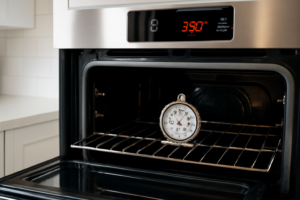
12. Turn the oven temperature dial to 350°F and wait 8-10 minutes—the element will glow bright orange-red across its entire surface when functioning correctly.
📝 Next Steps: This post will be expanded by Claude AI with:
- Detailed step-by-step instructions with explanations
- Safety warnings and precautions
- Tool recommendations and usage tips
- Troubleshooting common issues
- Product recommendations (repair kits, tools) from Amazon via Firecrawl
- Affiliate links integrated naturally into sentence form
🔧 Recommended Parts & Tools
You can find the replacement part you need, such as this Frigidaire 316075103 Oven Bake Element for Electric Ranges and Stoves, on Amazon. For this repair, you’ll need a WB44K10005 WB44K10001 Oven Bake Element Suitable for GE Hotpoint Americana Ov… which includes all the necessary components. You can find the replacement part you need, such as this Beaquicy WB44X200 Bake Element Replacement for GE 240V oven element wb44x200 …, on Amazon. You can find the replacement part you need, such as this Beaquicy WB44X5082 Oven Bake Element – Replacement for Hot-point G-E Kenmore …, on Amazon. You can find the replacement part you need, such as this Ismosm 4Pcs Nut Driver Set RC Tool Set Hex Nut Driver for RC Vehicle RC Helic…, on Amazon.
As an Amazon Associate, I earn from qualifying purchases.
How Much Does This Repair Cost?
Replacement bake elements for the GE JB645RKSS typically run $25–$40 for a quality OEM or compatible part. Hiring a professional technician for this repair will usually cost $150–$250 once you factor in the service call fee and labor, making this one of the best DIY value repairs you can do.
Recommended Products
These are the parts and tools we recommend for this repair, based on compatibility and customer reviews:
- GE WB44X200 Genuine OEM Lower Bake Element 240V for GE Electric Ovens
- AMI PARTS WB44X200 Bake Heating Element Fit for G-E Stove Oven JKP27*08, JKP62GK1, JKP07J6, JKP16G, JKP27, JKP38G, JKP40G, JKP47G, JRP03*J1 Replace AP2031031, WB44X0160, WB44X160, WB44X200R, WB44X6200
- Beaquicy WB44X200 Bake Element Replacement for GE 240V oven element wb44x200 – Suitable for jkp07g*d2, jkp16g*07, jkp16g*d1, jkp16g*d2, jkp16g*h1, jkp16g*j3, jkp16gj4, jkp16gj5,jkp16gj6 and more OVENS
- GE Appliances WB44X5082 Genuine OEM Bake Element for Ranges
As an Amazon Associate, I earn from qualifying purchases.