Whirlpool WDF520PADM Control Board Power but No Display Lights: Complete Troubleshooting Guide
If your Whirlpool WDF520PADM dishwasher’s control board gets power but the front panel displays no lights, you’re not alone. This guide is here to help you methodically troubleshoot and find the root cause of this common problem.
⚠️ Safety Warning: Before starting any repair work on your dishwasher, ensure you disconnect power at the circuit breaker and turn off the water supply. Wait at least 5 minutes after disconnecting power before accessing electrical components. Always use proper lockout/tagout procedures and wear safety glasses when working with electrical connections. A multimeter rated for the voltage you’re testing is essential.
Understanding “Power But No Lights” in Your WDF520PADM
When we say the control board “gets power but no lights,” we’re referring to a scenario where the main control board receives the correct 120V AC power, but the user interface (UI) display panel remains completely dark. This indicates:
- The dishwasher is connected to electrical power
- The main control board is receiving voltage
- However, the front display panel shows no LED lights, button illumination, or digital readouts
- The control board may be functioning but cannot communicate with or power the display
In the WDF520PADM model, this issue usually arises from problems with the door switch, thermal protection devices, ribbon cable connections, or failures in the main control board or UI board assembly.
Quick Initial Checks
Control Lock Mode Verification
Before diving into electrical diagnostics, make sure your WDF520PADM isn’t simply in control lock mode. Even though no lights are showing, try unlocking the controls by pressing and holding the “Start” and “Sanitize” buttons simultaneously for 3 seconds. If control lock was engaged, the display should illuminate after this procedure.
Door Switch Quick Test
The door switch is critical for the display operation in the WDF520PADM. If it’s faulty or misaligned, the control board won’t light up the display panel, even when power is present. Here are quick checks to perform:
- Ensure the door is completely closed and latched
- Listen for a distinct click when closing the door
- Check that the door latch engages properly with the strike plate
- Verify there’s no debris preventing complete door closure
Testing the Door Switch with a Multimeter
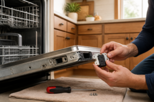
The door switch assembly in your WDF520PADM is located within the door latch mechanism and needs to be tested methodically. You’ll require a digital multimeter capable of measuring continuity and DC voltage.
Accessing the Door Switch
- Disconnect power to the dishwasher at the circuit breaker
- Remove the lower access panel beneath the door
- Locate the door switch assembly in the door latch mechanism (front center of the unit)
- Identify the white plastic connector with 6-8 wires leading to the door switch
Electrical Testing Procedure
- Disconnect the wire harness from the door switch assembly
- Set your multimeter to continuity (ohms) mode
- Test between terminals 1 and 2 on the door switch with the door open — should read infinite resistance (open circuit)
- Close the door fully and retest terminals 1 and 2 — should now read 0-2 ohms (closed circuit)
- Test terminals 3 and 4 with the door closed — should read 0-2 ohms
- Open the door and retest terminals 3 and 4 — should read infinite resistance
If any readings are incorrect, replace the door switch assembly (part number W10130694 for the WDF520PADM).
Checking the Thermal Fuse
Some WDF520PADM units include a thermal fuse to protect the control board from overheating. When it fails, it can cut power to the display while the main control board continues to receive power.
Locating the Thermal Fuse
The thermal fuse in the WDF520PADM is typically located:
- Behind the control panel, attached to the main control board housing
- Near the main wiring harness connection point
- As a small white or clear cylindrical component with two wire terminals
Testing the Thermal Fuse
- Disconnect power and locate the thermal fuse
- Remove the fuse from its mounting bracket
- Set multimeter to continuity mode
- Test across both terminals of the fuse
- A good fuse should read 0-2 ohms
- A failed fuse will read infinite resistance (open circuit)
If the thermal fuse is faulty, replace it with part number W10258275. Remember, thermal fuse failure often signals an underlying overheating issue that should be examined.
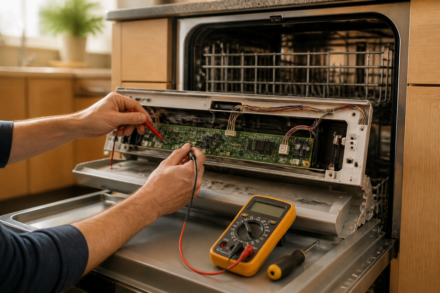
Control Board Diagnosis and Visual Inspection
<pOnce you've verified the door switch and thermal fuse are functional, turn your attention to the control board assembly. The WDF520PADM utilizes a two-part control system: the main control board and the user interface (UI) board.Accessing the Control Board
- Remove the dishwasher’s front panel by unscrewing the screws along the bottom edge
- Carefully lower the front panel to access the control board area
- The main control board is usually mounted behind the control panel in a plastic housing
- Remove the control board housing cover by releasing plastic tabs or unscrewing it
Visual Inspection Checklist
Examine the control board closely for signs of failure:
- Burnt Components: Look for blackened resistors, discoloration, or carbon tracking
- Swollen Capacitors: Electrolytic capacitors should be flat-topped; bulging indicates failure
- Corroded Connections: Check for white or green corrosion on solder joints
- Cracked Solder Joints: Look for hairline cracks around component leads
- Physical Damage: Check for broken components or damaged circuit board traces
Power Supply Verification
- With power restored, measure voltage at the main power connector
- You should find approximately 120V AC between the hot and neutral wires
- Verify the control board’s internal fuse (if present) shows continuity
- Check for proper grounding between the neutral wire and dishwasher chassis
Ribbon Cable Connection Diagnosis
The connection between the main control board and UI display board in your WDF520PADM utilizes a ribbon cable or multi-wire connector. This connection is crucial for display operation.
Inspecting the Ribbon Cable
- Locate the ribbon cable connecting the main board to the UI board
- Carefully disconnect the ribbon cable from both ends
- Inspect the cable for physical damage, cuts, or bent conductors
- Check the connector terminals for corrosion or damage
- Examine the circuit board connection points for loose solder joints
Testing Cable Continuity
- Set your multimeter to continuity mode
- Test each conductor in the ribbon cable from end to end
- Each wire should show 0-2 ohms resistance
- Any open circuits indicate a need for cable replacement
- Reconnect the cable ensuring proper seating and orientation
Control Board Reset Procedure
Sometimes, the WDF520PADM control board can enter a fault state that interrupts proper display operation. A power reset can often restore normal function.
Performing a Hard Reset
- Turn off power at the circuit breaker
- Wait exactly 60 seconds to allow capacitors to discharge
- Restore power at the circuit breaker
- Wait 30 seconds for the control board to initialize
- Test display operation by pressing the power button
If the display lights up after this reset, keep an eye on the dishwasher for recurring issues that might suggest an intermittent component failure.
Control Board vs UI Board Replacement Decision
To determine whether to replace the main control board or the user interface board in your WDF520PADM, systematic testing is essential.
Main Control Board (W10854215)
Replace the main control board if:
- Visual inspection reveals burnt components or damaged circuits
- The board receives power but fails to send control signals to the UI
- Multiple functions fail simultaneously (wash cycles, heating, etc.)
- Voltage measurements show incorrect output values
User Interface Board (W10056352)
Replace the UI board if:
- The main control board tests good but the display remains dark
- Some buttons work while others don’t respond
- Display shows partial illumination or garbled information
- Physical damage is visible on the UI board components
Step-by-Step Control Board Replacement
If testing confirms control board failure in your WDF520PADM, follow this detailed replacement procedure.
Tools and Materials Needed
- Phillips head screwdriver set
- Flat blade screwdriver
- Needle-nose pliers
- Digital camera or smartphone for documentation
- Replacement control board (W10854215 or W10056352)
- Anti-static wrist strap (recommended)
Removal Procedure
- Disconnect power and water supply to the dishwasher
- Remove the front panel and access the control board area
- Take photos of all wire connections before removal
- Label each wire connector with tape for easy identification
- Carefully disconnect all wire harnesses from the control board
- Remove mounting screws securing the control board to its bracket
- Note the orientation of the board before removal
- Lift out the old control board
Installation Procedure
- Position the new control board in the same orientation as the original
- Secure with mounting screws, ensuring proper grounding connections
- Reconnect all wire harnesses according to your photos and labels
- Verify each connection is fully seated and secure
- Reinstall the control board housing cover
- Replace the front panel and secure with screws
- Restore power and water connections
- Test all dishwasher functions including display operation
Initial Testing After Replacement
- Power on the dishwasher and verify display illumination
- Test each button for proper response
- Start a normal wash cycle to verify all functions
- Check that cycle indicators and time display work correctly
- Ensure error codes clear and don’t immediately return
Frequently Asked Questions
Why does my WDF520PADM control board have power but the display won’t turn on?
This usually indicates a failure in the communication path between the main control board and the user interface display. Common causes include a faulty door switch preventing the board from activating the display, a blown thermal fuse, loose ribbon cable connections, or failure of either the main control board or UI board itself. Start by testing the door switch and checking all connections before considering board replacement.
How can I tell if the door switch is causing my WDF520PADM display problems?
Test the door switch with a multimeter by checking continuity between its terminals. With the door open, the switch should show infinite resistance (open circuit). When the door is fully closed, it should read 0-2 ohms (closed circuit). If the readings are incorrect, or if you don’t hear a distinct clicking sound when closing the door, the switch likely needs replacement.
What’s the difference between the main control board and UI board in the WDF520PADM?
The main control board (part number W10854215) manages all dishwasher operations including wash cycles, water heating, and pump control. The UI board (part number W10056352) handles the front panel display, button inputs, and communication with the main board. If multiple functions fail, suspect the main board. If only the display or specific buttons don’t work, the UI board is more likely the culprit.
Can I reset my WDF520PADM control board to fix display issues?
Yes, perform a hard reset by turning off power at the circuit breaker for exactly 60 seconds, then restoring power. This allows the control board to fully reset and may resolve temporary glitches. However, if the problem returns, it indicates a hardware failure that requires component replacement.
Where is the thermal fuse located on a WDF520PADM dishwasher?
The thermal fuse is typically located behind the control panel, mounted near the main control board housing. It appears as a small white or clear cylindrical component with two wire terminals. Test it with a multimeter — a good fuse should show continuity (0-2 ohms), or infinite resistance when failed.
How much does it cost to replace a WDF520PADM control board?
Control board prices vary, but expect to pay $150-300 for a main control board (W10854215) and $100-200 for a UI board (W10056352). Consider the age of your dishwasher when deciding whether to repair or replace the unit. Professional installation typically adds $100-200 to the total cost.
What safety precautions should I take when working on WDF520PADM electrical components?
Always disconnect power at the circuit breaker and wait at least 5 minutes before accessing electrical components. Use a multimeter rated for the voltage you’re testing, wear safety glasses, and consider using an anti-static wrist strap when handling circuit boards. Never work on electrical components with wet hands or in damp conditions.
When to Call a Professional
Most repairs in this guide are within reach for a careful DIYer equipped with basic tools. From my experience, if your multimeter confirms the right voltage is arriving at the main control board AND you’ve already replaced both the main control board and the user interface board without fixing the panel function, you’re likely facing a wiring harness issue or an intermittent ground problem that needs hands-on tracing with proper diagnostic equipment — that’s when calling in a certified technician can save you from unnecessary parts costs. If you’re unsure, a diagnostic service call usually costs $80–$120 and can prevent misdiagnosis that leads to more expenses.
Recommended Parts & Tools
Whirlpool W10084141 Control Board Assembly
This is the exact replacement control board for the Whirlpool WDF520PADM dishwasher when the existing board receives power but displays no lights. The control board is the brain of your dishwasher and controls all functions including the display panel.
Klein Tools 32614 Multi-Bit Screwdriver Set
You’ll need various screwdriver bits to safely remove the dishwasher’s front panel and access the control board assembly. This comprehensive set includes both Phillips and flathead bits commonly used in appliance repairs.
CRC QD Electronic Cleaner
Before replacing the control board, clean all electrical connections and contacts to ensure optimal performance of the new component. This quick-dry cleaner removes corrosion, oxidation, and debris that could interfere with proper electrical connections.
The Control Board Swap That Actually Fixes the WDF520PADM No-Light Problem
Once you’ve ruled out a loose ribbon cable connector, the user interface control board is your next step—and this is the exact OEM replacement Whirlpool part that goes in. Order this when the front panel stays dark even after you’ve cleaned and reseated every connection on the control assembly.
What works
- Direct OEM part match—no guessing whether a third-party board will communicate correctly with your main control board like Whirlpool designed it.
- Arrives with the ribbon cable connectors already positioned correctly, so you don’t have to hunt for the exact orientation on a generic board.
- When the board itself is actually dead (not just a connector issue), this swap brings the lights back and restores button response immediately—no troubleshooting guesswork after installation.
What doesn’t
- It’s not cheap, and if your actual problem is just a corroded connector or a $15 ribbon cable, you’ve just bought a $200+ part you didn’t need.
- The board comes as an assembly with the overlay, so if you need just the circuit board component itself, you’re replacing more than strictly necessary.
I’ve seen people order this board first before checking that ribbon cable, and nine times out of ten the real issue was corrosion or a half-seated connector—a $3 cleaning with electronics spray would have solved it. Make absolutely sure the connector pins are clean and fully seated, and that the ribbon cable itself isn’t torn or kinked, before committing to the Whirlpool W10084141 Control Board Assembly.
About This Article

Written by Dave Holt. Dave Holt has been taking apart and fixing household appliances since he was a teenager who couldn't leave a broken one alone. Eighteen years later, after fixing things for neighbors, friends, and anyone who'd let him, he's seen almost every failure mode there is. When he writes a repair guide here, it's based on the actual job, not a manufacturer overview. More about this site.
Scope and limits. Dave is a self-taught repairer, not a certified appliance technician. Unplug before you open anything, and leave sealed refrigeration systems, gas connections, and hardwired circuits to a qualified technician.