Complete Repair Guide for LG WM3400CW: Spider Arm Failure, Hall Sensor Issues, and LE Error Code
The LG WM3400CW front-load washer is a reliable appliance, but like all washers, it can develop issues over time. Three of the most common problems affecting this model are spider arm failure, hall sensor malfunction, and the LE error code. This comprehensive guide will walk you through understanding these issues, diagnosing them accurately, and performing the repairs yourself.
Understanding the LE Error Code on the LG WM3400CW
The LE error code on the LG WM3400CW indicates a locked rotor or rotor position sensor failure. This error means the washer’s control board has detected that the drum motor cannot rotate freely, or the sensor that monitors rotor position is malfunctioning. The WM3400CW uses a direct-drive motor system, which is more efficient than belt-driven models but more sensitive to rotor position detection issues.
When you see the LE error code on your WM3400CW display, the washer will typically stop mid-cycle and refuse to complete the wash. The motor may hum without spinning, or the drum may not rotate at all. This error can be caused by several underlying issues: a failed hall sensor, a mechanical blockage in the drum, internal motor failure, or a compromised rotor position sensor circuit.
The LE code is the washer’s way of protecting itself from damage. If the rotor cannot move, continuing to operate could burn out the motor windings or cause electrical damage to the control board. Understanding this error code is your first step toward diagnosis and repair.
What Is the Spider Arm and Why Does It Fail?
Spider Arm Anatomy and Function
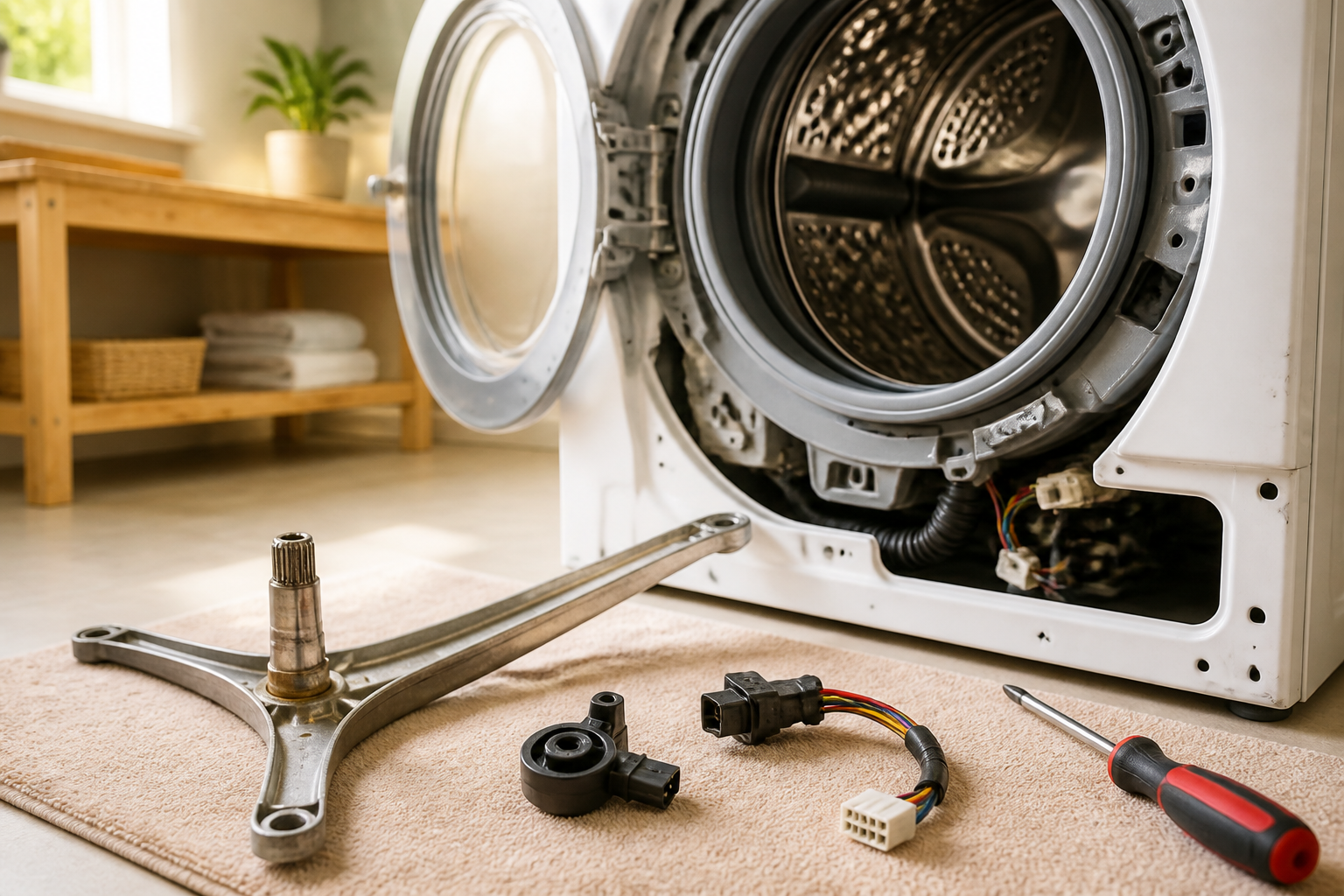
The spider arm on the LG WM3400CW is a three-pronged metal support structure that holds the front of the drum bearing assembly. It’s called a “spider” because of its leg-like appearance. This component is bolted to the back of the drum and extends backward into the tub. The spider arm carries the entire weight of the drum and all the wet clothes inside it during the spin cycle, which can involve forces exceeding 300 pounds of downward pressure.
On the WM3400CW, the spider arm is made of cast metal and connects the drum to the tub via sealed bearings. These bearings allow the drum to spin freely while supporting the load. The spider arm is a critical component for proper drum alignment and balance.
Why Spider Arms Fail
Spider arms fail for several reasons on the WM3400CW. Normal wear and tear over many years eventually fatigues the metal. Overloading the washer with excessive clothes concentrates stress on the spider arm bearings. Calcium deposits and detergent residue can accumulate inside the tub, creating friction against the spinning drum and forcing the spider arm to work harder. Manufacturing defects in earlier production runs of the WM3400CW have also been documented, causing some units to experience premature spider arm failure after just 3-5 years.
Symptoms of Spider Arm Failure on the WM3400CW
- Drum wobble or side-to-side movement: You can feel or see the drum moving laterally, especially during the spin cycle. This indicates the spider arm is no longer properly supporting the drum’s front position.
- Metal shavings or metallic debris: Finding gray or silver metal particles in the lint trap, on clothes, or at the bottom of the tub is a red flag. These particles come from bearing wear as the spider arm deteriorates.
- Loud banging or grinding noises: As the spider arm weakens, the drum can contact the tub wall. This creates loud metallic banging sounds during the spin cycle. Grinding sounds indicate bearing material is being damaged.
- Clothes getting caught: A misaligned drum can create gaps where fabric catches, tearing clothes and potentially damaging the drum seal.
- Burning smell: Friction from a failing spider arm bearing can generate heat and a burnt rubber or metal smell.
- Water leaking from the front seal: Drum misalignment puts pressure on the front tub seal, potentially causing leaks.
- Difficulty starting wash cycles: A severely misaligned drum may prevent the door latch from engaging properly.
The Hall Sensor on the LG WM3400CW: Location and Function
Is the Hall Sensor Built Into the Motor?
A common question about the WM3400CW is whether the hall sensor is built into the motor. The answer is no—the hall sensor is not built into the motor itself. Instead, on the WM3400CW direct-drive motor system, the rotor position sensor (hall sensor) is mounted separately on the stator assembly.
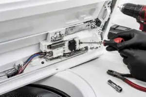
Hall Sensor Location on the WM3400CW
The hall sensor on the WM3400CW is located on the back stator assembly, which sits at the very back of the washer drum cavity. To locate it precisely: remove the back panel of your WM3400CW by unbolting it from the rear. Once the panel is off, look at the rear motor assembly. You’ll see the stator—a flat, disc-shaped metal component with copper wire windings. The hall sensor is a small black rectangular component approximately 1 inch long and 0.5 inches wide, mounted directly to this stator assembly with one or two screws.
The hall sensor has a three-wire connector: one red wire (power), one black wire (ground), and one yellow or green wire (signal). The sensor detects magnetic field changes from the rotor magnets as the rotor spins. This information is sent to the control board, which uses it to time electrical pulses to the motor windings for proper rotation and speed control.
Why Hall Sensor Failure Causes the LE Error
When the hall sensor on the WM3400CW fails, it stops sending rotor position data to the control board. Without this information, the control board cannot determine if the rotor is actually moving. It interprets this lack of feedback as a locked rotor condition and triggers the LE error code. This is a safety mechanism—the board assumes the motor is stalled and shuts down operation to prevent damage.
⚠️ Safety Warning
Before beginning any repair on the WM3400CW, unplug the washer from the electrical outlet. Do not attempt repairs with power connected. The motor in the WM3400CW operates at 240 volts, which is lethal. Even with the washer unplugged, internal capacitors can store dangerous charges. Wait at least 5 minutes after unplugging before touching internal components. If you’re uncomfortable working with electrical components, consult a professional technician.
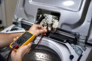
Testing the Hall Sensor with a Multimeter
Multimeter Preparation
To test the hall sensor on your WM3400CW, you’ll need a digital multimeter set to measure resistance (ohms) or DC voltage. A basic multimeter costing $20-40 will work fine. Ensure the WM3400CW is unplugged before beginning.
Testing Procedure
- Remove the back panel of the WM3400CW by unbolting all fasteners along the bottom and sides.
- Locate the hall sensor connector on the stator assembly at the rear of the motor cavity. It’s a three-pin plastic connector.
- Carefully disconnect this connector by gently pulling it straight out.
- Set your multimeter to the resistance setting (ohms). On most meters, this is marked with the omega symbol (Ω).
- Touch the red probe to the red wire terminal and the black probe to the black wire terminal in the connector. A working hall sensor should show between 150-500 ohms. If your meter shows 0 ohms (short circuit) or infinite resistance (open circuit), the sensor is defective.
- With the WM3400CW still unplugged, use a non-contact voltage tester to ensure no power is present at the connector before proceeding.
- Manually rotate the rotor by hand. Watch for any resistance change on your multimeter as you rotate. A functioning hall sensor’s resistance may fluctuate slightly as the rotor position changes, indicating the magnetic field detection is working.
Interpreting Your Test Results
If resistance is 150-500 ohms and stable: The hall sensor is likely functioning. The LE error may be caused by something else, such as spider arm misalignment preventing the rotor from turning.
If resistance is 0 ohms: The sensor is shorted and needs replacement.
If resistance is infinite or the meter shows “OL” (overload): The sensor is open-circuited and has failed internally. Replacement is necessary.
If resistance fluctuates wildly or erratically: The sensor connection is corroded or the sensor is failing. Replacement is recommended.
Accessing the Rotor and Stator: Back Panel Removal
Tools Needed
- Adjustable wrench or socket set (10mm and 13mm sockets typically)
- Torx screwdriver set (T15 and T25 bits)
- Multimeter
- Container for small parts
- Clean cloth or paper towels
- Rotor bolt removal tool (can use a rubber mallet and socket if no specialized tool available)
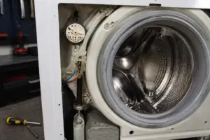
Back Panel Removal Steps
- Ensure the WM3400CW is unplugged and the power cord is not accessible during your work.
- Close the washer door and remove the detergent dispenser drawer by sliding it straight out.
- Move the WM3400CW away from the wall to access the back. You’ll need clearance to remove the back panel.
- Locate the bolts holding the back panel. On the WM3400CW, there are typically six bolts: four along the bottom edge and two on the sides near the top. Use a 10mm or 13mm socket (depending on your model year) to remove these bolts.
- Carefully pull the back panel straight toward you. There may be a thin wire harness connecting the panel to the main assembly—if present, disconnect it gently.
- Set the back panel on a clean surface where it won’t be damaged. Do not lay it face-down, as this can bend internal components.
Rotor Bolt Removal
Once the back panel is off your WM3400CW, you’ll see the rotor—a cylindrical metal component in the center of the motor assembly. The rotor is held in place by a single large bolt (typically 24mm) threaded into the motor shaft. This bolt is torqued extremely tight during manufacturing.
To remove the rotor bolt on your WM3400CW:
- You’ll need a rotor bolt socket or a 24mm socket with a very sturdy breaker bar or impact wrench. The bolt typically requires 30-50 foot-pounds of torque to loosen.
- The bolt usually has a reverse thread, meaning it loosens by turning clockwise (opposite of normal bolts). Check your service manual to confirm the direction for your specific WM3400CW year.
- If the bolt won’t budge with a standard wrench, try tapping the breaker bar with a rubber mallet while applying steady pressure. Do not strike the socket directly, as this can damage it.
- Some technicians use a rubber mallet to gently tap the rotor itself while applying counter-pressure with the socket. This can help break the bolt loose without damaging the shaft.
- Once the bolt is loose, remove it completely and set it aside in a safe location. You’ll reinstall this same bolt after sensor replacement.
- Carefully slide the rotor straight toward you. It may require gentle rocking to free it from the motor shaft.
Rotor Position Sensor (Hall Sensor) Replacement Procedure
Parts Required
For the LG WM3400CW, the hall sensor part number is 6501KW2002A or updated equivalent 6501KW2002B. Always verify the correct part number for your specific WM3400CW serial number by checking the manufacturer’s manual or parts database, as minor variations exist between production years.
Sensor Replacement Steps
- With the rotor removed from your WM3400CW, you now have full access to the stator assembly at the back.
- Locate the hall sensor mounted on the stator. It’s the small black rectangular component with a three-wire connector.
- Disconnect the three-wire connector by gently pulling it straight out. If it’s corroded or stuck, wiggle it gently side-to-side while pulling.
- The sensor is held to the stator by one or two small screws, typically T15 Torx head. Remove these screws and set them aside in a small container.
- Carefully lift the old hall sensor away from the stator. Note its exact orientation—the sensor must be installed in the same position.
- If the mounting surface is corroded or dirty, wipe it clean with a dry cloth. Do not use water or solvents, as these can damage internal stator components.
- Position the new hall sensor in the identical location. The three-wire connector should face the same direction as the original.
- Install the mounting screws, tightening them firmly but not excessively. Over-tightening can crack the plastic sensor body. These screws should be snug—approximately 1-2 foot-pounds of torque.
- Reconnect the three-wire connector. Ensure it’s fully seated—you should hear a slight click if the connector uses a locking tab.
- Before reassembling, manually rotate the rotor by hand and check with your multimeter that the new sensor reads 150-500 ohms and shows resistance variation as the rotor moves.
Spider Arm Replacement: Complete Procedure
Parts Required
The spider arm part number for the LG WM3400CW is 4280EA4001T or 4280EA4001S, depending on your model year. Some replacement kits include the bearing assembly, while others provide just the spider arm casting. Verify your exact part number against your WM3400CW serial number.
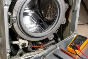
Accessing the Spider Arm
The spider arm on the WM3400CW is located behind the drum, so you must remove the drum to access it. This is a more involved repair than hall sensor replacement.
- Unplug the WM3400CW from the electrical outlet and wait 5 minutes.
- Remove the back panel using the procedure detailed above.
- Disconnect the rotor bolt and remove the rotor as described in the “Rotor Bolt Removal” section.
- Locate the front drum bearing cover—a large circular metal plate on the back of the drum. This cover holds the spider arm in place.
- On the WM3400CW, the bearing cover is bolted to the drum with multiple bolts (typically 8-12 bolts in a circular pattern). Remove all these bolts using a 10mm or 13mm socket. Place them in a small container to avoid losing them.
- Carefully pull the bearing cover straight toward you. This may require slight rocking if it’s tight. Do not pry with a screwdriver, as this can damage the sealing surfaces.
- Once the cover is off, the spider arm becomes visible. On the WM3400CW, it’s a three-pronged metal structure bolted to the back of the drum at three points.
- Support the drum weight with a helper or use a hydraulic floor jack with a wooden block to prevent it from falling as you remove the spider arm bolts.
- Remove the three bolts holding the spider arm to the drum. These are typically 13mm or 15mm bolts and may be very tight due to factory torque specs (usually 30-50 foot-pounds).
- Once all three bolts are removed, carefully pull the spider arm toward the rear, away from the drum. It may have sealed bearings that require gentle wiggling to free.
Installing the New Spider Arm on Your WM3400CW
- Before installation, inspect the replacement spider arm. It should appear identical to the original, with three evenly-spaced legs and mounting holes that align with the drum.
- Position the new spider arm so its legs extend toward the rear of the tub. The mounting surface should face the rear of the drum.
- Insert the three mounting bolts through the spider arm holes and into the threaded holes in the drum. These bolts must be torqued to the specification in your WM3400CW service manual, typically 35-45 foot-pounds. Tighten them in a star pattern (alternating positions) to ensure even pressure.
- Once the spider arm is secure, carefully inspect for any interference with the tub. Rotate the drum by hand and confirm it moves freely without catching.
- Reinstall the bearing cover over the spider arm. Align the bolt holes carefully.
- Install all bolts in the bearing cover using a criss-cross or star pattern for even seating. Torque these bolts to approximately 15-20 foot-pounds.
- After the bearing cover is installed, reinstall the rotor by sliding it onto the motor shaft and torquing the rotor bolt to 40-50 foot-pounds (remember, this likely has reverse thread).
- Reinstall the back panel and all its fasteners.
- Before plugging in the WM3400CW, rotate the drum by hand through a complete revolution to ensure nothing is catching or misaligned.
How to Clear the LE Error After Repair
Once you’ve completed repairs to your WM3400CW (whether hall sensor replacement or spider arm repair), the LE error code should clear automatically when you run the next wash cycle. The control board will re-evaluate the rotor position sensor signal or
Recommended Parts & Tools
LG Washer Spider Arm Assembly Replacement
The spider arm is the primary component failing in the WM3400CW, as it supports the drum and can crack or wear out over time, causing the LE error code. This genuine LG replacement part ensures proper drum alignment and operation. Check current pricing on Amazon.
iFixit Essential Electronics Toolkit
Accessing the spider arm and hall sensor on your LG washer requires removing panels and internal components, making a quality screwdriver set and socket tools essential. This comprehensive toolkit includes all the drivers and extractors needed for safe disassembly without stripping fasteners. Check current pricing on Amazon.
LG Washer Hall Sensor Replacement Part
The hall sensor monitors drum position and triggers the LE error when it malfunctions or becomes disconnected. Replacing this sensor along with the spider arm ensures both the mechanical support and electronic detection systems work properly. Check current pricing on Amazon.
The Spider Arm Assembly That Stops the Drum-Won’t-Turn Problem Cold
If your WM3400CW drum isn’t spinning or is making grinding noises during the wash cycle, the spider arm is usually the culprit—and it’s the first part I replace before chasing sensor issues. This assembly failure is what actually prevents water and detergent from reaching the drum properly, and it’s a straightforward swap if you catch it early.
What works
- Bolts directly into the same mounting points as the factory part—no modification or adapter fussing required on this model.
- Comes pre-assembled, which saves you 20 minutes of fiddling with the individual spokes and clips inside the drum housing.
- Once installed, the drum spins smoothly again and the grinding noise disappears immediately—a real confidence builder that you ordered the right part.
What doesn’t
- Installation still requires draining the tub and removing the front panel—plan on 45 minutes to an hour of work, not a 10-minute job.
- Won’t fix the LE error code if it’s actually caused by a Hall sensor malfunction rather than mechanical arm failure—you’ll need to diagnose which issue you actually have first.
The real friction point I’ve hit: replacing the spider arm without first confirming the sensor isn’t the actual problem means you’ll end up ordering a second part and pulling the washer apart twice. Run a continuity test on the Hall sensor before you order anything, or at minimum, listen carefully to whether the drum physically won’t turn or if it turns but the washer stops with an error code. Get the LG Washer Spider Arm Assembly Replacement when you’re confident the arm itself is cracked or worn.
This post contains affiliate links. As an Amazon Associate, I earn from qualifying purchases at no extra cost to you.