Inverter Board Replacement on Panasonic NN-SN966S Countertop Microwave
The inverter board in the Panasonic NN-SN966S is a critical component that controls the microwave’s power output and cooking functions. Unlike traditional microwaves that use transformers, this model utilizes advanced inverter technology to provide consistent power delivery. When the inverter board fails, it’s typically due to power surges, component aging, or thermal stress from prolonged use. This repair is classified as ADVANCED due to the high-voltage components involved and the precision required for proper installation. The inverter board failure will completely disable the microwave’s heating function, though the display and turntable may continue to operate normally.
Symptoms
- Microwave powers on with normal display function but produces no heat during cooking cycles
- Intermittent heating with power cutting in and out during operation
- Display shows error code H97, H98, or H99 specifically on the Panasonic NN-SN966S
- Unusual humming or buzzing sounds from the right side of the unit during attempted heating
- Microwave immediately shuts down when START button is pressed, returning to standby mode
- Sparking or arcing visible through the ventilation slots on the right side panel
⚠️ Safety Warning
Microwave repair involves extremely dangerous high-voltage components. The Panasonic NN-SN966S contains a high-voltage capacitor that can retain a lethal charge (up to 4,000 volts) even when unplugged for extended periods. Before beginning any work, the capacitor must be properly discharged using an insulated screwdriver across its terminals. Always disconnect power and wait at least 10 minutes before opening the unit. Wear rubber-soled shoes and avoid working in damp conditions. The magnetron and inverter circuits operate at potentially fatal voltages. If you are not completely comfortable working with high-voltage electrical systems, contact a certified appliance repair technician immediately.
Parts Needed
- Panasonic Inverter Board Assembly – Part Number NNST969WRPE or A603Y6D60AP (verify compatibility with serial number)
- High-temperature electrical contact cleaner
- Dielectric grease for connector protection
- Cable ties (4-inch minimum length) for wire management
- Anti-static wrist strap to prevent component damage
Tools Required
- Phillips head screwdriver (size #2)
- Insulated flathead screwdriver for capacitor discharge
- Digital multimeter with high-voltage capability
- Needle-nose pliers with insulated handles
- Flashlight or headlamp for interior visibility
- Anti-static wrist strap
- Wire nuts (22-14 AWG capacity)
Step-by-Step Instructions
Step 1: Power Disconnection and Safety Preparation
🔨 Pro Tip from Dave
When disconnecting the high-voltage capacitor on the NN-SN966S, don’t trust that it’s discharged just because the unit has been unplugged — I always discharge it manually across the terminals using a 20,000-ohm, 2-watt resistor, because I’ve seen these hold a lethal charge for over 24 hours after power loss. Also, photograph the ribbon cable orientation before you disconnect it from the inverter board, because the connector is keyed in a way that looks reversible but isn’t, and installing it backwards will destroy your new board instantly.
Unplug the Panasonic NN-SN966S from the wall outlet and allow it to sit for a minimum of 10 minutes. Clear a stable work surface with adequate lighting. Position the microwave so the right side panel is easily accessible. Attach your anti-static wrist strap to an unpainted metal surface on the microwave chassis. Gather all tools and parts before proceeding to avoid extended exposure to internal components.
Step 2: Right Side Panel Removal
Remove the four Phillips head screws securing the right side panel of the Panasonic NN-SN966S. These screws are located at each corner of the panel – two at the top edge, approximately 2 inches from front and back, and two at the bottom edge in corresponding positions. Carefully slide the panel toward the back of the unit approximately 1/2 inch, then lift it away from the chassis. Set the panel aside in a safe location to avoid damage.
Step 3: High-Voltage Capacitor Discharge
Locate the large cylindrical capacitor mounted on the right side interior wall. Using your insulated flathead screwdriver, carefully short the two terminals together while avoiding contact with the metal shaft. You should see a small spark – this is normal and indicates successful discharge. Repeat this process twice more at 30-second intervals to ensure complete discharge. Use your multimeter to verify zero voltage across the capacitor terminals before proceeding.
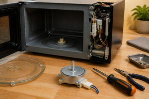
Step 4: Inverter Board Location and Access
The inverter board in the Panasonic NN-SN966S is mounted vertically behind the magnetron assembly, approximately 6 inches from the front of the unit. It appears as a green circuit board roughly 4 inches by 6 inches with multiple wire harness connections. You’ll need to carefully move some wire harnesses aside to gain full access. Take a digital photograph of all connections before disconnecting anything to ensure proper reassembly.
Step 5: Wire Harness Disconnection
Identify the five main connector blocks attached to the inverter board. Starting from the top: the 6-pin white connector controls communication signals, the 4-pin red connector handles thermal monitoring, the 2-pin black connector manages the magnetron drive, and two additional connectors for power input and ground connections. Carefully pull each connector straight out from the board – do not twist or rock them as this can damage the connection pins.
Step 6: Inverter Board Mounting Screw Removal
The inverter board is secured to the chassis with three Phillips head screws. The top screw is located directly above the board mounting bracket, approximately 1 inch from the top edge. The bottom two screws are positioned at the lower corners of the mounting bracket, spaced approximately 3 inches apart. Remove these screws completely and place them in a small container to prevent loss.
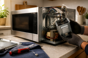
Step 7: Failed Board Removal
With all connections disconnected and mounting screws removed, carefully lift the failed inverter board straight up and out of the Panasonic NN-SN966S chassis. The board may require slight manipulation to clear surrounding components. Inspect the mounting bracket for any signs of heat damage or corrosion that might indicate additional problems requiring attention before installing the replacement board.
Step 8: New Board Preparation and Installation
Remove the replacement inverter board from its anti-static packaging only when ready to install. Position the new board in the mounting bracket, ensuring it sits flush against all mounting points. The component side of the board should face toward the interior of the microwave. Reinstall the three mounting screws in reverse order of removal, tightening to finger-tight plus one-quarter turn – do not overtighten as this can crack the circuit board.
Step 9: Wire Harness Reconnection
Using your reference photograph, reconnect all five wire harness connectors to the new inverter board. Each connector is keyed to prevent incorrect installation, but verify proper alignment before applying pressure. Push each connector firmly until you hear or feel a positive click indicating full engagement. Gently tug each connector to confirm secure attachment.
Step 10: Initial Testing and Verification
Before reassembling the chassis, reconnect power and perform a preliminary test. Set the Panasonic NN-SN966S to heat a microwave-safe cup of water for 30 seconds at 50% power. The unit should operate normally without error codes. If successful, disconnect power again and proceed with reassembly. If errors occur, double-check all connections and verify the replacement board part number matches your specific model.
Step 11: Chassis Reassembly
Carefully route all wire harnesses back to their original positions, ensuring none are pinched or stressed. Reinstall the right side panel by reversing the removal process – align the panel tabs, slide forward until flush, then install the four corner screws. Tighten screws evenly to avoid panel warping, but do not overtighten as this can strip the mounting holes.
Step 12: Final Testing and Calibration
Reconnect power and perform a comprehensive test of the Panasonic NN-SN966S functions. Test heating at various power levels, verify proper turntable rotation, and confirm all display functions operate correctly. Run a full 2-minute heating cycle to ensure sustained operation without shutdown or error codes. The repair is complete when all functions operate within normal parameters.
Troubleshooting
- If error codes persist after board replacement, verify all wire harness connections are fully seated and check for damaged connector pins
- No heating after installation may indicate a faulty magnetron that damaged the original board – test magnetron continuity across filament terminals (should read 2-3 ohms)
- Intermittent operation suggests loose connections or inadequate mounting screw tightness – recheck all attachment points
- Display flickering or random shutdowns may indicate power supply issues requiring additional circuit board replacement
- Unusual noises during operation could signal magnetron failure or improper board grounding – verify chassis ground connections
- If the replacement board fails quickly, investigate for voltage fluctuations or inadequate ventilation causing thermal damage
When to Call a Professional
- Multiple component failures are suspected, indicating a more complex electrical problem requiring diagnostic equipment
- High voltage measurements outside normal parameters suggest magnetron or transformer issues beyond inverter board scope
- Repeated inverter board failures indicate underlying electrical problems requiring circuit analysis and repair
- Any uncertainty about high-voltage safety procedures or component identification warrants professional intervention
When to Call a Professional
Most of the repairs in this guide are within reach for a careful DIYer with basic tools. In my experience, if your NN-SN966S is showing signs of arcing inside the cavity, producing a burning smell from the magnetron area rather than the control panel, or if your resistance measurements across the magnetron filament leads are reading open or shorted, you’re looking at a failed magnetron rather than an inverter board — and magnetron replacement on this unit involves direct exposure to the high-voltage circuit in a way that I’d only recommend for technicians with proper metering equipment and hands-on HV training. When in doubt, a diagnostic service call typically costs $80–$120 and can save you from a misdiagnosis that costs more in parts.
Recommended Parts & Tools
Panasonic Microwave Inverter Board Assembly A608Y3X00AP
This genuine Panasonic inverter board is designed specifically for the NN-SN966S model and other compatible Panasonic microwaves. The inverter board controls the microwave’s power output and cooking functions, making it an essential replacement part when experiencing heating issues or error codes. This OEM part ensures proper fit and reliable performance for your Panasonic NN-SN966S countertop microwave. Check current pricing on Amazon.
Klein Tools 32500 Multi-Bit Screwdriver with 14 Bits
This professional-grade screwdriver set includes all the necessary bits for safely disassembling your Panasonic NN-SN966S microwave during inverter board replacement. The kit includes Phillips, flathead, and Torx bits that are commonly used in microwave repairs, along with a comfortable grip handle for precise control. Having the right tools ensures you won’t strip screws or damage components during the repair process. Check current pricing on Amazon.
Understanding Panasonic Inverter Board Repair
The inverter board is the technological core that sets Panasonic microwaves apart from conventional models. Unlike traditional microwaves that cycle their magnetron on and off at full power to simulate lower settings, the inverter board continuously converts household 120V AC into precisely regulated variable DC power delivered directly to the magnetron. This allows the magnetron to operate at true reduced power levels, producing more consistent heating and better food results. The board achieves this through a switching power supply circuit built around an IGBT (Insulated Gate Bipolar Transistor), high-voltage capacitors, and a control IC — components that work under significant electrical stress every time the microwave runs a cooking cycle.
Because these components operate near their thermal and electrical limits during normal use, panasonic inverter board repair has become one of the most frequently searched microwave service topics. The three most common failure points are electrolytic capacitor degradation, IGBT transistor burnout, and cracked solder joints caused by repeated thermal expansion and contraction cycles. Capacitors dry out over years of use and lose their ability to filter voltage properly, often causing erratic power output or complete failure. The IGBT, which handles the high-frequency switching at the heart of the inverter circuit, can fail suddenly if the microwave experiences a power surge or is run while the cooling fan is obstructed. Hairline cracks in solder joints around high-current traces are subtler but equally disruptive, creating intermittent faults that are difficult to diagnose without a magnifying glass and a multimeter.
Distinguishing inverter board failure from magnetron failure is an important diagnostic step before purchasing any parts. A failed inverter board typically produces symptoms such as the microwave running normally — turntable spinning, interior light on, control panel responsive — but generating no heat whatsoever, or heating only at full power regardless of the selected setting. You may also observe a burned smell originating from the control cavity rather than the cooking cavity, or see a visible burn mark on the board itself. By contrast, a failing magnetron more commonly produces a loud buzzing or humming noise during operation, arcing inside the cooking cavity, or a sharp burning odor that smells distinctly like ozone. If the unit trips your circuit breaker repeatedly, the inverter board’s IGBT is a primary suspect. Running through these symptom checks carefully before ordering components will save time and money on any panasonic inverter board repair attempt.
Once you have confirmed the inverter board is the source of the problem, you face a practical decision: attempt component-level repair or replace the entire board. Component-level panasonic inverter board repair is technically possible — a skilled technician can replace a failed IGBT, reflow cracked solder joints, or swap out a bulging capacitor for a fraction of the cost of a new board. However, this work requires SMD soldering proficiency, access to a temperature-controlled soldering station, a digital multimeter capable of testing capacitance and diode junctions, and a clear understanding of the lethal voltages stored in microwave capacitors even when the unit is unplugged. For most homeowners, the risk profile and skill requirements make full board replacement the more sensible path. Replacement boards for the NN-SN966S are readily available from Panasonic authorized parts suppliers and third-party vendors, and swapping the entire assembly — as detailed in the steps above — restores the microwave to full function without requiring any specialized electronics knowledge beyond basic hand tools and careful attention to safety protocols.