Door Switch Replacement on Panasonic NN-SN686S Countertop Microwave
The door switch assembly in the Panasonic NN-SN686S is a critical safety component that prevents the magnetron from operating when the door is open. This microwave model features three door switches working in conjunction: two normally-open switches that close when the door is properly seated, and one normally-closed switch that opens when the door is closed. When these switches fail, they can cause the microwave to not start, continue running with the door open (extremely dangerous), or blow the main fuse repeatedly. This repair is rated as MODERATE difficulty due to the need to discharge the high-voltage capacitor and navigate around sensitive electronic components, but it can be completed by a competent DIY repairer with proper safety precautions.
Symptoms
- Microwave will not start despite display showing normal function and door appearing properly closed
- Main fuse (20A, 250V) blows immediately when door is closed and start button is pressed
- Intermittent operation where microwave works sometimes but fails to start other times with same door position
- Display shows “door open” error message even when door is firmly closed and latched
- Microwave starts but stops after 1-2 seconds of operation
- Unusual clicking or buzzing sounds from the door latch area when closing the door
⚠️ Safety Warning
Microwave ovens contain high-voltage components that can deliver lethal electrical shock even when unplugged. The high-voltage capacitor in the Panasonic NN-SN686S stores approximately 2100 volts and must be properly discharged before beginning any repair work. Never attempt this repair with the unit plugged in. Always discharge the capacitor using an insulated screwdriver across the terminals before touching any internal components. The magnetron, high-voltage transformer, and capacitor remain energized for several minutes after unplugging. Wear safety glasses and insulated gloves throughout this procedure. If you are not comfortable working with high-voltage electrical components, contact a qualified appliance repair technician.
Parts Needed
- Primary door switch (Panasonic part number F630Y8G00XP) – normally open, SPST, 16A rating
- Secondary door switch (Panasonic part number F630Y8G00XP) – identical to primary switch
- Monitor switch (Panasonic part number F630Y8G01XP) – normally closed, SPST, 16A rating
- Door switch mounting bracket if damaged (part number F603Y5M00XP)
- Wire nuts or crimp connectors if wire replacement is needed (16-14 AWG capacity)
Tools Required
- Phillips head screwdriver (size #2)
- Flathead screwdriver with insulated handle for capacitor discharge
- Digital multimeter with continuity testing capability
- Needle-nose pliers with insulated handles
- Wire strippers (16-14 AWG)
- Flashlight or headlamp for interior illumination
- Insulated work gloves rated for electrical work
Step-by-Step Instructions
Step 1: Preparation and Power Disconnection
🔨 Pro Tip from Dave
On the NN-SN686S, the monitor switch wiring harness connector sits directly behind the door latch hook channel and is under slight tension from the factory — if you don’t relieve that tension before seating the new switch, the connector will micro-crack the switch housing within a few hundred cycles and you’ll be back in there doing the same job again. Route the harness with a slight forward loop before snapping it in, and that failure mode disappears entirely.
Unplug the Panasonic NN-SN686S from the electrical outlet and wait at least 5 minutes before proceeding. Remove any items from inside the microwave cavity and ensure the turntable and support ring are removed. Place the unit on a stable work surface with adequate lighting. The door switches are located on the right side of the door frame, so position the microwave to provide easy access to this area.
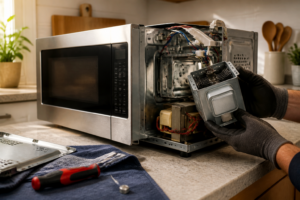
Step 2: Remove the Outer Cabinet
Remove the four Phillips screws from the bottom panel of the Panasonic NN-SN686S – two at the front edge and two at the rear edge. Remove the three screws along the left side panel, located approximately 2 inches from the front, middle, and rear of the unit. Carefully slide the outer cabinet toward the rear of the unit and lift it off. The cabinet should come away cleanly, exposing the internal components and control board assembly.
Step 3: Discharge the High-Voltage Capacitor
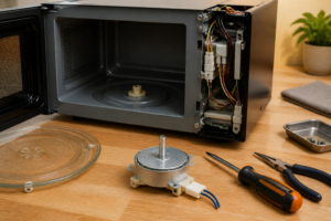
Locate the high-voltage capacitor mounted on the right side of the unit – it appears as a cylindrical component approximately 4 inches tall with two wire terminals on top. Using an insulated screwdriver, carefully touch both terminals simultaneously to discharge any stored voltage. You may see a small spark – this is normal. Repeat this process three times to ensure complete discharge. Never touch the terminals with your bare hands or uninsulated tools.
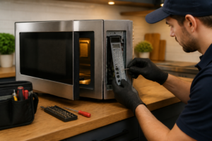
Step 4: Access the Door Switch Assembly
The door switch assembly in the Panasonic NN-SN686S is mounted on the right side of the door frame, behind a plastic cover. Remove the two Phillips screws securing the plastic switch cover – these are located on the inside edge of the microwave cavity frame. The switch assembly will now be visible, showing three individual microswitches mounted in a vertical arrangement.
Step 5: Test the Existing Switches
Before removal, test each switch with your multimeter set to continuity mode. With the door open, the top and middle switches (normally open) should show no continuity. The bottom switch (normally closed/monitor switch) should show continuity. Press each switch actuator manually – the top and middle switches should close and show continuity when pressed, while the bottom switch should open and show no continuity when pressed.
Step 6: Disconnect the Wire Harnesses
Each door switch has a two-wire connector. The top switch connects to a white and blue wire harness, the middle switch connects to white and black wires, and the bottom monitor switch connects to white and red wires. Carefully disconnect these connectors by pressing the plastic retaining tabs and pulling straight out. Do not pull on the wires themselves as this can damage the connections.
Step 7: Remove the Faulty Switches
Each switch is secured by two Phillips screws in a vertical mounting bracket. Remove the screws from the switch you’re replacing – they are located on either side of each switch body. The switches are mounted with approximately 0.75 inches of vertical spacing between centers. Keep track of which switch came from which position as they have different electrical characteristics.
Step 8: Install the New Door Switches
Mount the new switches in the exact same positions as the original switches. The two normally-open switches (top and middle positions) are identical Panasonic part F630Y8G00XP. The bottom monitor switch is part F630Y8G01XP (normally closed). Secure each switch with its two mounting screws, ensuring the switch actuators are properly aligned with the door latch mechanism.
Step 9: Reconnect the Wire Harnesses
Reconnect the wire harnesses to their respective switches: white/blue to the top switch, white/black to the middle switch, and white/red to the bottom monitor switch. Ensure each connector clicks securely into place and cannot be pulled loose with gentle tugging. Verify that no wires are pinched or stressed in the connection area.
Step 10: Test Switch Operation
With your multimeter still connected, manually test each new switch by pressing the actuators. Verify the normally-open switches close when pressed and the normally-closed monitor switch opens when pressed. Close the microwave door and verify that all three switches actuate properly when the door latches – you should hear distinct clicking sounds from each switch.
Step 11: Reassemble the Cabinet
Replace the plastic switch cover and secure it with the two Phillips screws removed in Step 4. Carefully slide the outer cabinet back over the internal assembly, ensuring no wires are pinched between the cabinet and internal components. The cabinet should slide forward easily and align with the front control panel.
Step 12: Final Testing
Secure the cabinet with all screws removed in Step 2. Plug the Panasonic NN-SN686S back into power and perform a functional test. Place a microwave-safe cup of water inside and run the unit for 30 seconds on medium power. The microwave should start normally, operate without interruption, and stop immediately when the door is opened during operation.
Troubleshooting
- If the microwave still won’t start after switch replacement, check the main fuse (20A, 250V) located near the power cord entry point – it may have blown due to the original switch failure
- If switches don’t actuate properly when door closes, check door alignment and ensure the door latches are not bent or damaged – they should engage the switch actuators with approximately 0.125 inches of travel
- If you hear arcing sounds during operation, immediately stop and verify all wire connections are secure and not touching any metal cabinet parts
- If the display shows random error codes after reassembly, ensure the control board ribbon cable wasn’t disturbed during cabinet removal
- If switches test correctly with multimeter but microwave behavior is unchanged, the control board may have sustained damage from the original switch failure
- If door won’t latch properly after switch installation, verify switches are mounted flush with the mounting bracket and actuator buttons aren’t binding
When to Call a Professional
- If you discover any burned or melted components during disassembly, as this indicates more extensive electrical damage requiring professional diagnosis
- If the high-voltage transformer shows signs of damage, oil leakage, or burn marks, as this component requires specialized handling and testing equipment
- If multiple fuses continue to blow after door switch replacement, indicating a more serious electrical fault in the magnetron or control circuits
- If you’re uncomfortable working around high-voltage components or lack experience with electrical repairs, as improper procedures can result in serious injury or death
When to Call a Professional
Most of the repairs in this guide are within reach for a careful DIYer with basic tools. In my experience, if you’ve tested all three switches and they check out fine but the microwave still won’t run or is blowing the line fuse repeatedly, you’ve crossed into territory involving the control board, the magnetron thermal cutout, or a compromised high-voltage capacitor — components where a wiring mistake or an undischarged capacitor can send 2,100 volts through you, and that’s the point where calling a certified tech isn’t timidity, it’s just good math. When in doubt, a diagnostic service call typically costs $80–$120 and can save you from a misdiagnosis that costs more in parts.
Recommended Parts & Tools
Panasonic Microwave Door Switch Assembly F630Y6M10BP
This genuine OEM door switch assembly is designed specifically for Panasonic microwave models including the NN-SN686S. The switch ensures proper door latch detection and prevents the microwave from operating when the door is open, making it an essential safety component. Check current pricing on Amazon.
CRAFTSMAN Screwdriver Set, Phillips and Slotted, 6-Piece
This precision screwdriver set includes the Phillips head and slotted drivers needed to safely disassemble the Panasonic NN-SN686S control panel and access the door switch mechanism. The comfortable grips and magnetic tips make working in tight spaces around microwave components much easier. Check current pricing on Amazon.