What Is a Backstab Electrical Outlet?
A backstab electrical outlet, also called a push-in outlet, features spring-clip terminals on the rear of the outlet body that accept wire inserted directly into small round holes. Unlike screw-terminal outlets where wire wraps around a brass or silver screw shaft and is clamped mechanically, backstab connections rely on an internal spring leaf or spring clip to grip the wire through friction and elastic force alone.
Here’s the critical technical distinction: When you insert a wire into a backstab hole, the wire pushes against a small spring leaf inside the outlet body. This spring is typically a thin strip of phosphor bronze or similar alloy, compressed to create contact pressure. The contact area between the wire’s copper surface and this spring leaf is approximately 8–12 square millimeters—roughly 1/10th the contact area of a properly wrapped screw-terminal connection. This small contact footprint is the root cause of virtually every backstab failure mode.
All major outlet manufacturers—Leviton, Pass & Seymour, Hubbell, Eaton, and others—sell the exact same outlet body with BOTH connection types: the round holes on the back are backstab terminals, and the screw terminals on the sides are for conventional clamping. The outlet doesn’t know the difference. A single outlet can have wires connected via backstab on one side and screw terminals on the other side. This is why identifying your outlet type requires physically inspecting the wiring, not just looking at the device itself.
Backstab outlets became common in residential wiring in the 1960s and 1970s as a labor-saving convenience—electricians no longer needed to form precise J-hooks with pliers or use screwdrivers to tighten terminals. Simply strip a half-inch of insulation, push the wire in, and move to the next connection. This speed advantage created a widespread adoption that persisted through the 1990s, despite growing evidence of reliability problems. Many older homes contain dozens or even hundreds of backstabbed outlets and switches.
⚠️ Why Backstab Connections Are Dangerously Unreliable
The physics of backstab failure is a self-reinforcing cycle:
When current flows through any electrical connection, resistive heating occurs. Ohm’s Law defines this: P = I²R, where P is power (heat in watts), I is current in amperes, and R is resistance in ohms. Consider a 15-ampere circuit operating at 120 volts. If a backstab connection develops just 0.1 ohms of resistance (which is not unusual for a partially loose connection), the heat generated at that single connection point is:
P = (15)² × 0.1 = 22.5 watts
To put this in perspective, a typical incandescent nightlight bulb consumes 4–7 watts. This single failing connection generates 3–5 times the heat energy of a nightlight, concentrated at a tiny contact point inside your outlet body—where there is no airflow and no heat dissipation mechanism. The outlet’s phenolic plastic body begins to soften around 150–160°C (300–320°F), and degradation accelerates above that temperature.
The thermal cycling mechanism: As the outlet heats during the day or when heavy loads are running, the wire and spring leaf expand. When the circuit is de-energized or the load is removed, both components cool and contract. Copper expands and contracts at a different rate than the phosphor bronze spring leaf. Over hundreds or thousands of thermal cycles—spanning months or years—the mechanical grip loosens incrementally. Each cycle reduces contact force slightly, raising resistance further, generating more heat, which accelerates the mechanical loosening. This is a positive feedback loop that ends in either arcing or complete connection failure.
Arcing and plasma formation: When a connection becomes loose enough that the wire no longer makes solid metal-to-metal contact, a gap forms. Current will jump this gap as an arc—essentially a plasma channel at temperatures exceeding 5,000°F (2,760°C). This arc is often not visible to the naked eye, especially inside an outlet body. The phenomenon is called incipient arcing when the gap is tiny and the arc occurs only momentarily during each AC cycle (120 times per second in North American 60 Hz power). The arc produces extreme heat at the contact points, oxidizing the copper and burning away the phosphor bronze spring. It also produces a distinctive electromagnetic signature—rapid, high-frequency current spikes—that modern AFCI (Arc Fault Circuit Interrupter) breakers are designed to detect.
AFCI tripping as a diagnostic clue: If a circuit with a backstab outlet trips an AFCI breaker repeatedly, especially when nothing is plugged in or when loads are light, the outlet is almost certainly experiencing incipient arcing. This is one of the most reliable diagnostic indicators of backstab failure. The AFCI is doing its job—interrupting a circuit that would otherwise continue degrading until combustion occurs. Do not ignore repeated AFCI trips. This is a red flag, not a nuisance.
Aluminum wiring + backstab connections = severe hazard: Homes built in the 1960s and 1970s sometimes contain aluminum branch wiring (circuit wiring to outlets) instead of copper, due to a temporary copper shortage. Aluminum is more prone to oxidation than copper. When aluminum oxidizes, a white or gray oxide layer forms on the surface. Aluminum oxide is an insulator—it blocks current flow. A backstab connection holding aluminum wire will experience increasing resistance as the oxide layer grows, even if the mechanical grip remains constant. The combination of thermal cycling loosening the connection AND oxide growth creating a film is uniquely dangerous. If you discover aluminum wiring in your home (it appears dull gray-silver rather than shiny copper), call a licensed electrician specializing in aluminum rewiring. This is not a DIY repair scenario.
Fire risk data: The National Fire Protection Association (NFPA) documents that loose electrical connections, including arcing connections, are responsible for approximately 10–15% of all residential electrical fires. The U.S. Fire Administration estimates these fires cause hundreds of deaths and thousands of injuries annually. While not every backstab outlet fails catastrophically, the statistical risk is substantial across a large population of homes, which is why fire-code officials and experienced electricians have increasingly rejected backstab connections over the past two decades.
Are Backstab Connections Legal Under the National Electrical Code?
This is a nuanced answer that varies by jurisdiction and changes with code updates.
The official NEC position: NEC Article 110.3(B) states that listed equipment must be installed in accordance with the instructions provided by the manufacturer. Almost all outlet manufacturers list their push-in (backstab) connections in fine print on the rear of the outlet body with a critical limitation: 14 AWG solid wire only. The listing explicitly excludes stranded wire and explicitly excludes 12 AWG and larger gauges.
This means that a backstab connection is legal under the NEC IF:
- The wire is 14 AWG (the standard gauge for 15-amp branch circuits in residential wiring)
- The wire is solid copper, not stranded
- The outlet manufacturer explicitly permits push-in connections (most modern outlets do, but older outlets sometimes do not—check the outlet body)
- Your local jurisdiction accepts the NEC as written (some jurisdictions adopt modified or stricter versions)
Practical reality differs from technical legality: Many professional electricians refuse to use backstab connections even where code technically permits them. Building inspectors vary widely: some will pass backstab connections on new installations if the wire gauge is correct, while others will reject them outright. Commercial and industrial electrical codes (governed by the National Electrical Code for commercial and industrial installations) almost universally prohibit backstab connections for any application. Insurance companies and code officials have been quietly discouraging backstab use for years.
Recent code trends: The 2023 NEC and several state electrical codes have begun restricting backstab connections further. Some jurisdictions now require screw terminals for all new work. Check with your local building department before assuming backstab connections are acceptable in your area. Even if your jurisdiction permits them, understanding the failure risk means many homeowners choose to replace them proactively with screw-terminal outlets for reliability rather than legal compliance alone.
How to Identify If Your Outlets Are Backstabbed
Safe visual inspection—step by step:
- Turn off the circuit breaker controlling that outlet. Flip the breaker to the OFF position. Then flip it back on momentarily to confirm the outlet went dead (a lamp plugged into it should turn off). Flip the breaker back to OFF. Never rely on visual confirmation or the switch position alone—always verify with a testing device.
- Test for voltage using a non-contact voltage tester (Fluke, Ideal, or Klein models cost $15–$30). Touch the tester to each outlet slot. The tester should give no indication—no light, no beep. If it detects voltage, the breaker is not the one controlling this outlet. Find the correct breaker and repeat.
- Remove the cover plate by unscrewing the single center screw. Some plates are painted over or stuck—work gently to avoid damaging the plate.
- Unscrew the outlet from the box by removing the two screws at the top and bottom of the outlet body. Pull the outlet forward carefully—it may have limited travel due to attached wires.
- Inspect the rear of the outlet body:
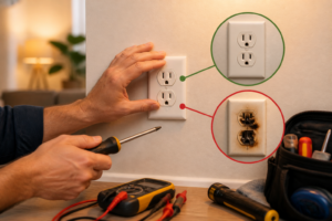
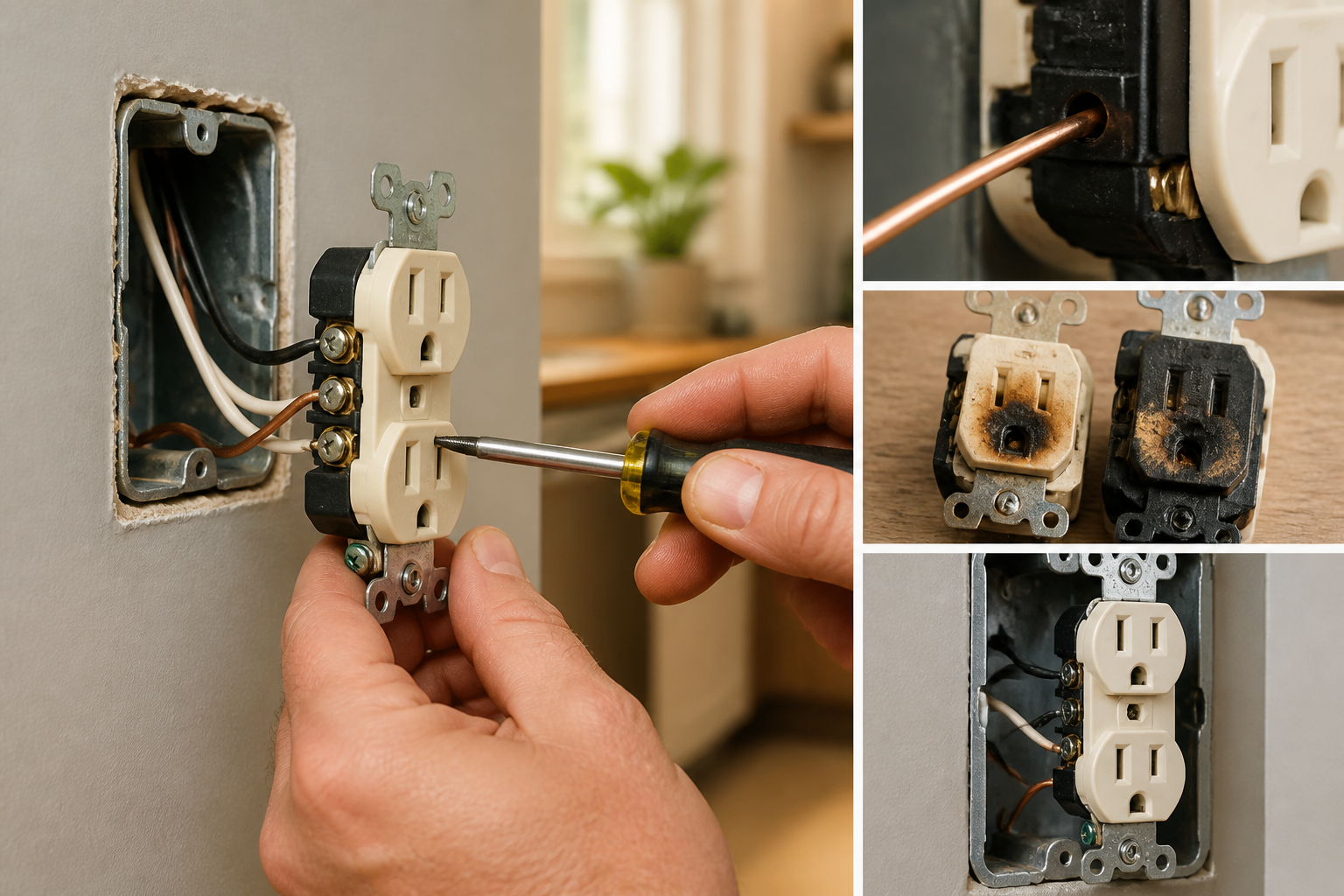
- Backstab connections: Small round holes (typically 3/32 to 1/8 inch diameter) on the back face of the outlet body. The hole appears smooth and round. Some holes may have a tiny slot next to them (the release slot for removing wires).
- Screw-terminal connections: Visible brass or silver screw shafts on the side edges of the outlet, with a circular hole through which the screw passes. The screw has a slot (for a flathead screwdriver) or a cross-hole (for a Phillips screwdriver). Wire wraps around the screw shaft in a J-hook shape.
- Mixed connections: Many outlets have backstabs on one side and screw terminals on the other—or even three wires, two backstabbed and one screw-terminal.
- Photograph the wiring before touching anything. Take close-up photos from multiple angles showing exactly which wires are connected where. This documentation is invaluable if something goes wrong or if you need to call an electrician.
- Note the wire gauge: Look at the insulation or the wire itself. Does it look thick or thin? 14 AWG wire has a diameter of approximately 0.064 inches (about 1.6 mm)—similar to a thick paper clip wire. 12 AWG is noticeably thicker. If you’re uncertain, measure the diameter with a caliper or ruler.
Signs of a failing backstab outlet (diagnosis without opening the outlet):
- The outlet or cover plate feels warm to the touch during normal use. A warm outlet is an abnormal condition. Electrical devices should not radiate significant heat unless they are designed to (like heaters or toasters).
- Lights flicker when that outlet is in use, or flicker on their own if they’re on the same circuit. This indicates voltage fluctuation caused by a rising connection resistance.
- The outlet stops working intermittently or only works when the plug is fully inserted at a specific angle. This suggests the mechanical contact is loose—pushing the plug at an angle increases pressure temporarily.
- Burning plastic smell near the outlet or in the room where that outlet is located. This is the phenolic outlet body or wire insulation degrading under excessive heat. This is an immediate hazard—stop using that outlet and call an electrician.
- AFCI breaker trips repeatedly when a device is plugged into that outlet, or even when nothing is plugged in. As discussed earlier, AFCI breakers detect incipient arcing. Repeated trips point directly to arcing at the outlet connections.
- Visible burn marks or discoloration around the outlet holes when you look at the back of the outlet body.
Testing a Suspected Backstab Outlet with Instruments
Basic outlet tester (3-light method):
A simple 3-light outlet tester (Sperry, Klein, or Extech models, $10–$20) plugs into the outlet and lights three indicator LEDs to show the outlet’s wiring configuration. The lights confirm correct polarity (hot, neutral, ground in the right positions) or reveal problems like reversed polarity, missing ground, or open ground. However, these testers do not detect a loose connection under no-load conditions. A backstab outlet can pass a 3-light test perfectly while the connection is loose and heating up under actual load.
Multimeter voltage drop test (the most revealing diagnostic for loose connections):
- Restore power to the circuit by flipping the breaker back on.
- Set a digital multimeter to AC voltage mode (usually marked with a V with a wavy line above it).
- No-load baseline: Touch the multimeter’s black probe to the large (neutral) slot and the red probe to the small (hot) slot of the suspected outlet. The reading should be 120V ±5% (i.e., 114–126V). Record this number. Then plug a standard lamp into an adjacent outlet on the same circuit and turn the lamp on. Re-measure the voltage at the suspected outlet. If the voltage dropped significantly (more than 2–3V), this suggests the circuit has high resistance somewhere. If this outlet has a backstab connection, it’s a prime suspect.
- Load test with high current draw: Now plug a high-current device into the suspected outlet itself—a space heater on high (1,500W), hair dryer, or toaster oven. Immediately (while the load is running) measure the voltage again at the outlet’s slots. Compare to the no-load reading. A voltage drop greater than 3–5V under load is a red flag. This drop indicates high resistance, and at a 15A circuit level, resistance at the outlet connection is the most likely cause. Calculate the approximate resistance: Using Ohm’s Law, R = V/I. If 15A causes a 5V drop at a single connection, that connection has approximately 0.33Ω of resistance—which is extremely high.
- Safety note: When measuring voltage on an energized circuit, keep one hand in your pocket and touch the probes with one hand only. Never let the probes slide and create a short circuit. Work deliberately and deliberately remove the load before removing the probes.
Thermal imaging (the visual confirmation):
An infrared thermometer ($20–$40) or thermal imaging camera ($300+) reveals heat patterns that are invisible to the naked eye. Point the infrared thermometer at the face of the suspected outlet (or directly at the cover plate) while a load is running. A normal outlet typically reads 75–90°F during use. A backstab outlet failing due to arcing or a loose connection can read 120–160°F or higher. Compare the temperature of the suspected outlet to an adjacent outlet on a different circuit—the temperature difference is telling. Thermal imaging is not a foolproof diagnostic (some failing connections don’t yet generate excessive heat), but it’s highly diagnostic when the suspected outlet is noticeably hotter than normal outlets.
How to Replace a Backstab Outlet with a Screw-Terminal Outlet
Tools and materials required:
- Non-contact voltage tester (to confirm power is off)
- Flathead and Phillips screwdrivers
- Needle-nose pliers (for forming J-hooks)
- Wire strippers (adjustable type, 8–10 inches long)
- Electrical tape (insulating tape for wire)
- Standard outlet tester (3-light, for final verification)
- New screw-terminal outlet (same voltage and amperage as the old one—15A 120V is standard residential)
- Wire nuts (if you’re daisy-chaining multiple cables to one outlet—typically 18–22 gauge rated)
- A flashlight or headlamp (working inside a dark electrical box is difficult)
Step-by-step replacement:
- Turn off the correct breaker. Flip the breaker controlling this outlet to OFF. Verify with the non-contact voltage tester on both the hot and neutral slots of the outlet. No beep or light = power is off.
- Remove the cover plate. Unscrew the single screw and carefully remove the plastic or metal cover plate.
- Unscrew the outlet from the electrical box. Remove the two screws (top and bottom) that attach the outlet mounting ears to the box. The outlet should now be free to pull forward. It may have limited travel because wires are still attached—work gently.
- Photograph the existing wiring. Before disconnecting anything, take detailed photos showing which wires are connected where. Label the wires in your mind: black (hot), white (neutral), bare copper or green (ground). Note if there are multiple cables (more than 3 wires total).
- Remove the wires from the backstab holes. If the outlet has a small release slot next to each backstab hole, insert a small flathead screwdriver into the slot and gently pull the wire straight outward. The spring will release. If there is no release slot, the wire is trapped and must be cut. Cut the wire close to the outlet with wire strippers (use the cutting blade on the stripper) and strip 3/4 inch of fresh insulation from the end of the wire.
- Inspect the copper wire ends. The exposed copper should be bright and shiny. If it appears dark, pitted, or oxidized, lightly sand the end with fine-grit sandpaper (220–400 grit) or use a wire brush to remove oxidation. Oxidized copper has high resistance and will not make a good connection at a screw terminal.
- Form a J-hook with each wire. Using needle-nose pliers, curl the wire end into a J-shape (a hook that looks like the letter J). The open end of the J should face clockwise when you look at the screw from the front. This orientation ensures that when you tighten the screw (turning clockwise), the screw handle moves in the same direction as the open end of the J, drawing the wire into the terminal rather than pushing it out. This is a critical detail that prevents the wire from being ejected from the terminal as you tighten the screw.
- Connect the wires to the screw terminals of the new outlet:
- Black (hot) wire: Goes to the brass screw terminal on the right side of the outlet when facing the front (plug-in side). The outlet body is typically polarized so that hot is on the right, neutral on the left, and ground at the bottom.
- White (neutral) wire: Goes to the silver screw terminal on the left side.
- Bare copper or green (ground) wire: Goes to the green screw terminal, usually at the bottom center.
- Tighten the screws firmly. The NEC specifies that screw terminals should be tightened to 12 inch-pounds of torque (approximately the tightness you’d apply with a standard flathead screwdriver using moderate hand pressure—not maximum force). A wire wrapped around a screw terminal and tightened to the correct torque will not pull free with a firm tug. If you have a torque screwdriver (specialty tool), set it to 12 in-lb, but most electricians rely on feel and a gentle pull-test to verify.
- Daisy-chaining multiple cables: If the electrical box contains more than one cable entering it (i.e., the box contains more than 3 wires), you may have a daisy-chain circuit where the circuit runs from one outlet to the next. The NEC requires that when multiple wires of the same color connect to a single terminal, they must be connected via a wire nut and pigtail. Here’s how: Connect all black wires together (from both cables) using a wire nut rated for the number and gauge of wires (typically a red or orange wire nut for two 14 AWG wires). Leave the nut slightly loose and extract a 6-inch pigtail of black wire from the bundle. Twist this pigtail into the nut with the others and tighten. Then connect this pigtail to the brass screw terminal. Repeat for white and ground. This distribution method ensures that no single terminal is bearing the full mechanical load of two wire connections.
- Fold wires accordion-style into the box. Gently push the outlet and wires back into the electrical box, forming the wires into smooth, flat loops rather than cramped coils. The wires should not be kinked or twisted sharply—tight bends in wire can create stress points that lead to breaks.
- Screw the outlet back into the box. Reinstall the two mounting screws (top and bottom) and tighten them snugly. The outlet should sit flush with the face of the electrical box (or slightly recessed if the box is recessed in the wall).
- Replace the cover plate and screw it down. Ensure it sits flat and covers the outlet evenly on all sides.
- Restore power by flipping the breaker back on.
- Test the new outlet with a 3-light outlet tester. Plug the tester into the outlet. If all three lights illuminate in the correct pattern (usually all three lit, or a specific pattern indicating correct polarity), the outlet is wired correctly. If lights indicate a fault (reversed polarity, missing ground, open ground), turn the breaker off immediately and recheck your connections against step 8.
Common mistakes to avoid:
- Not verifying power is off before working. Always use a voltage tester. Touching a live 120V terminal is painful and dangerous.
- Forming the J-hook backwards (with the open end facing counterclockwise). This causes the wire to slip out as you tighten the screw, leaving a loose connection.
- Not stripping enough insulation. The J-hook should be formed on bare copper, not on insulation. If insulation is wrapped around the screw, the connection is between insulation and metal, not copper and metal, and will have high resistance and fail quickly.
- Stripping too much insulation. If more than about 1 inch of insulation is removed, the bare copper can flex inside the outlet box and accidentally contact another conductor, creating a short
Recommended Tools & Products
Klein Tools Voltage Tester Pen
Before working on any electrical outlet, you need to verify that power is off to prevent dangerous shocks. This non-contact voltage tester quickly and safely detects live electrical current without direct contact, making it essential for identifying which outlets are still energized. Check current pricing on Amazon.
Leviton Decora Tamper-Resistant Outlet
When replacing failed backstab outlets, you’ll want to install a quality replacement receptacle with side-wire terminals instead of backstab connections, which are more reliable and safer for long-term use. Leviton’s tamper-resistant outlets provide superior durability and meet modern safety standards. Check current pricing on Amazon.
Wiha Insulated Screwdriver Set
Removing and installing outlet terminals requires precision screwdrivers that won’t damage wire connections or strip screw heads on tight fixtures. Insulated screwdrivers provide additional safety protection when working with electrical components, even with power off. Check current pricing on Amazon.
The Voltage Tester That Saves You from Backstab Outlet Diagnostics Guessing
Before you pull an outlet or start rewiring, you need to confirm the outlet is actually dead and safe to work on—and a voltage tester eliminates the guesswork that backstab outlets create. I’ve seen too many DIYers assume a loose backstab connection is the problem when it’s actually a breaker issue or a wiring fault upstream.
What works
- Confirms power is actually off before you touch any wires—non-contact design means you don’t have to probe into the outlet holes directly, which is a real safety win with backstabs.
- Instantly identifies which outlets on a circuit are live and which are dead, so you can map whether the problem is a single bad backstab connection or something bigger.
- Compact enough to carry in your pocket, and the audible beep cuts through the noise of diagnosing multiple outlets in a row without squinting at a display.
What doesn’t
- Won’t tell you the exact voltage or amperage—it’s a yes-or-no safety check, not a troubleshooting multimeter, so you’ll still need other tools for deeper electrical diagnostics.
- Requires good battery life to be reliable; I’ve had the batteries die at the worst moment, so swap them annually even if it hasn’t beeped in a while.
The first time I diagnosed a backstab outlet problem without confirming power was off, I got a nasty jolt that taught me the hard way—a Klein Tools Voltage Tester Pen should be the first thing you touch to any outlet before you touch anything else.
This post contains affiliate links. As an Amazon Associate, I earn from qualifying purchases at no extra cost to you.