How to Replace and Rewire the Lid Latch Switch on a GE Top-Load Washer
The lid switch is one of the most commonly replaced components on GE top-load washers. Whether your GTW465ASNWW won’t start because the lid won’t close properly, or your GTW725 has a stuck electronic lid lock, understanding the difference between mechanical and electronic latch systems is essential for proper diagnosis and repair. This guide covers everything you need to know about GE washer lid switches, including wiring diagrams, replacement procedures, and manual release techniques.
Understanding GE Lid Switch Systems: Mechanical vs. Electronic
Mechanical Lid Switch (GTW465 and Older Models)
Older GE top-load washers like the GTW465ASNWW use a mechanical lid switch assembly mounted under the washer’s top panel. This switch is a simple electrical component that physically closes when the lid is lowered and opens when the lid is lifted. The mechanical action of closing the lid activates a spring-loaded plunger inside the switch, completing the circuit that allows the wash cycle to begin.
The mechanical lid switch on the GTW465 contains three terminals: one for the hot/live wire (typically black), one for the neutral wire (typically white), and one for the signal wire that communicates with the control board. When the lid is down, these contacts complete a circuit that sends a “lid closed” signal to the washer’s main control board.
Electronic Lid Lock (GTW725 and Newer Models)
The newer GE GTW725 uses an electronic lid lock system rather than a simple mechanical switch. This solenoid-based lock is controlled by the main control board and serves two functions: it locks the lid during the wash cycle to prevent accidental opening, and it sends a signal to the control board confirming the lid’s position. Unlike the GTW465, the GTW725 lid lock is actively powered during the wash cycle rather than simply acting as a passive switch.
The electronic lid lock on the GTW725 requires both power (hot and neutral wires) and a signal wire to function properly. When power is removed from the washer, a manual release mechanism allows you to unlock the lid manually—an important feature when the electronic system fails.
GE Lid Latch Switch Wiring Diagrams and Terminal Functions
GTW465 Mechanical Lid Switch Wiring
The mechanical lid switch on the GTW465ASNWW has three terminals arranged in a line on the back of the switch housing:
- Terminal 1 (Hot/Line): Black wire (120V AC from the power source). This provides the electrical power to the switch circuit.
- Terminal 2 (Neutral/Return): White wire that returns power to the neutral bus. This completes the circuit.
- Terminal 3 (Signal): Yellow or pink wire that connects to the main control board. This wire sends the lid-closed signal to the control circuitry.
When the lid is down and the plunger is activated, continuity exists between the Hot and Signal terminals. The control board monitors this signal line for a continuous 120V reading (approximately 110-120V AC when measured with a multimeter). If the control board detects an open circuit on the signal line, it will not allow the wash cycle to start and may display an error code.
GTW725 Electronic Lid Lock Wiring
The electronic lid lock on the GTW725 operates differently from the GTW465. The lock has four terminals:
- Terminal 1 (Hot/Line): Black wire (120V AC). Powers the solenoid lock mechanism.
- Terminal 2 (Neutral/Return): White wire. Returns power to the neutral bus.
- Terminal 3 (Signal Out): Yellow wire. Sends a “lid closed” signal to the control board.
- Terminal 4 (Ground): Green or bare copper wire. Safety ground connection.
The key difference in the GTW725 system is that the solenoid lock is continuously powered during operation. The control board sends 120V AC to the solenoid coil, which creates an electromagnetic field that locks the lid. The signal wire independently communicates the lid’s position to the control board. This dual-function design is why the GTW725 can display an error if the lid lock fails even when the lid is physically closed.
⚠️ Safety Warning: Electrical Hazards
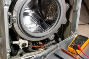
⚠️ CRITICAL SAFETY INFORMATION: Before working on any GE washer lid switch, you must unplug the appliance from the electrical outlet or turn off the circuit breaker that supplies power to the unit. Even after unplugging, the washing machine may retain a residual electrical charge in the capacitor or other components. Wait a minimum of five minutes after unplugging before touching internal components. When testing circuits with a multimeter, always set the meter to AC voltage mode and never touch both probe tips simultaneously to energized terminals. Never attempt to bypass or permanently disable the lid switch for operational use—this creates a serious safety hazard. The lid switch prevents the washer tub from spinning while the lid is open, which could cause severe lacerations or entanglement injuries. Temporary bypassing for diagnostic testing only is acceptable and covered in the testing section below.
Tools and Equipment Needed
Before you begin, gather the following tools:
- Multimeter (digital or analog) for testing continuity and voltage
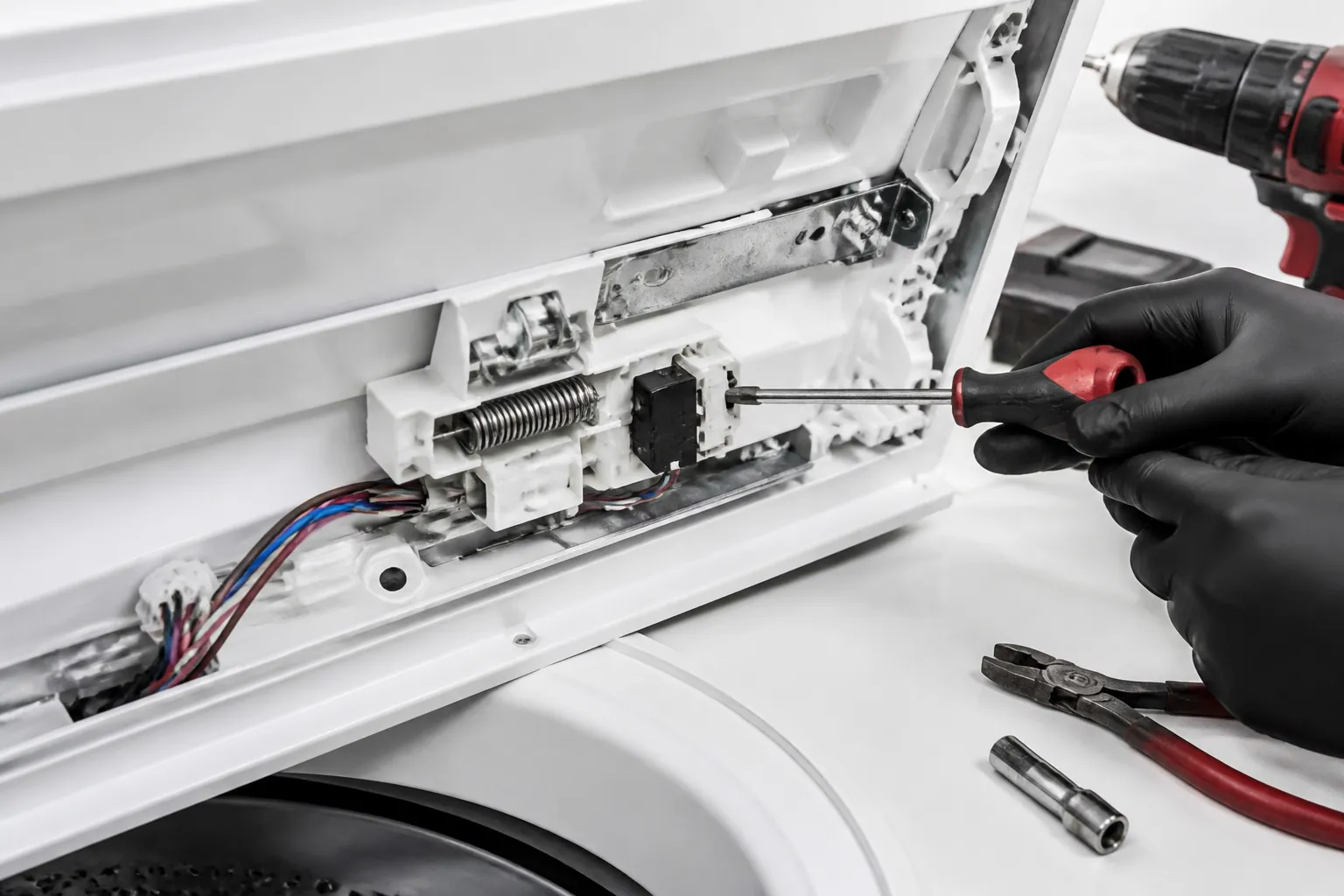
- Screwdriver set (Phillips and flathead, various sizes)
- Socket wrench set (usually 1/4″ and 3/8″ drive for fasteners holding the top panel)
- Panel removal tool or plastic pry bar to safely remove the top cover without scratching
- Wire strippers for preparing wire connections
- Crimp tool for attaching wire terminals (if your replacement switch uses crimp connectors)
- Needle-nose pliers for manipulating small connectors and springs
- Flashlight or headlamp for visibility inside the washer cabinet
- Small container for organizing fasteners during disassembly
Safely Testing the Lid Switch: Temporary Bypass Procedure
When to Bypass (Diagnostic Testing Only)
A temporary bypass is useful for determining whether the lid switch is actually faulty or whether the problem lies elsewhere in the control circuit. This procedure should only be used for testing and must be reversed immediately after diagnosis. Never operate a washer with a permanently bypassed lid switch.
GTW465 Mechanical Switch Bypass Procedure
- Unplug the GTW465ASNWW from the electrical outlet. Wait five minutes.
- Remove the top panel by unbolting the fasteners at the rear and lifting the panel straight up.
- Locate the lid switch assembly mounted on the underside of the top panel, near the left front corner. The switch has a white connector block with three wires.
- Pull the connector straight out from the switch. Do not force it—it should slide out smoothly.
- Using a jumper wire (a short piece of insulated copper wire with stripped ends), create a temporary connection between the Hot (black) and Signal (yellow/pink) terminals in the connector block. Simply insert the jumper wire ends into the appropriate terminal slots while leaving the connector unplugged from the switch.
- Plug the washer in and test whether it will start a wash cycle with the lid closed. If the cycle begins, the control board is functioning, and the switch is likely faulty.
- Immediately unplug the washer and remove the jumper wire. Reconnect the original switch connector.
GTW725 Electronic Lid Lock Bypass Procedure
- Unplug the GTW725 from the wall outlet. Wait five minutes for residual charge to dissipate.
- Remove the top panel by unbolting four bolts on the rear edge of the panel.
- Locate the electronic lid lock assembly at the top-left corner of the washer’s interior. It has a white four-pin connector.
- Carefully disconnect the four-pin connector by pressing the release tab and gently pulling the connector away from the lock assembly.
- Create a temporary jumper wire connection between the Hot (black terminal) and Signal Out (yellow terminal) in the connector block. Leave the connector unplugged from the lock.
- Plug the washer in. The lid should no longer be locked, and you should be able to start a cycle. If this allows the cycle to begin, the control board is functioning, but the lock assembly or its solenoid is faulty.
- Immediately unplug the washer and remove the jumper. Reconnect the original four-pin connector to the lock assembly.
How to Access the Lid Switch: Removing the Top Panel
GTW465ASNWW Top Panel Removal
- Unplug the washer from the electrical outlet.
- Locate the two bolts at the rear corners of the top panel, underneath the top edge. These are typically 1/4″ hex bolts.
- Using a 1/4″ socket wrench, remove both bolts. There are also typically two bolts under the front of the panel—you may need to tilt the panel slightly to access these.
- Carefully lift the top panel straight up and set it on a clean surface. Do not force it—if it resists, check that all bolts are fully removed.
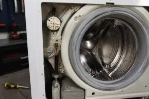
- You now have access to the lid switch assembly, which is mounted on the underside of the top panel using two screws.
GTW725 Top Panel Removal
- Unplug the GTW725 from the electrical outlet.
- Locate the four bolts around the top panel perimeter—two at the rear corners and two along the sides near the front.
- Remove all four bolts using the appropriate socket wrench (typically 3/8″ or 1/2″ depending on your model).
- Lift the top panel straight upward. On the GTW725, you may also need to disconnect a small water level float tube attached to the bottom of the panel—this is a flexible plastic tube that simply pulls off.
- The electronic lid lock assembly is mounted on the top-left corner of the interior. It is secured with two bolts and has a four-pin connector that must be unplugged before the lock can be removed.
Step-by-Step Lid Switch Replacement on GTW465ASNWW
Removing the Faulty Mechanical Switch
- After removing the top panel, locate the mechanical lid switch on the underside of the panel. The switch is a small rectangular component approximately 2 inches long with a plunger on the bottom that activates when pressed.
- The switch is held in place by two Phillips head screws on the mounting bracket. Remove both screws and set them aside.
- Gently pull the switch assembly away from the mounting bracket. The three-wire connector will come with the switch.
- To disconnect the wires, either unplug the connector block (if using push-in connectors) or use needle-nose pliers to carefully extract each terminal from the connector block if using crimp-style connections.
- If the wires are crimped to terminals, note the wire colors and their corresponding terminal positions before removal. You may want to take a photo with your phone for reference during reinstallation.
Installing the Replacement Switch on GTW465
- Obtain the replacement lid switch assembly. For the GTW465ASNWW, the correct part number is WH12X10558 or the equivalent assembly WH01X10074. Verify the part number matches your specific model by checking the washer’s serial plate on the side panel.
- If the new switch has loose wires that need to be connected to the existing connector block, strip approximately 1/4″ of insulation from each wire end.
- Insert the black (hot) wire into the first terminal position of the connector block. Push firmly until it clicks in place.
- Insert the white (neutral) wire into the second terminal position. Again, push until fully seated.
- Insert the yellow or pink (signal) wire into the third terminal position. Ensure all three wires are fully inserted and show no signs of backing out.
- Align the new switch with the mounting bracket on the underside of the top panel. The plunger should face downward and should align with the center of the bracket opening.
- Insert the two Phillips head screws through the mounting bracket and into the switch body. Tighten firmly but do not over-tighten, as the plastic housing can crack.
- Before reassembling, test the switch manually by pressing the plunger downward. You should hear a soft click as the internal contacts activate. Release the plunger and listen for another click as the contacts open. This confirms the mechanical action is working.
Step-by-Step Lid Lock Replacement on GTW725
Removing the Electronic Lid Lock Assembly
- After removing the top panel and exposing the interior, locate the electronic lid lock assembly in the top-left corner of the washer. It is a cylindrical solenoid component approximately 3 inches long.
- Disconnect the four-pin connector by pressing the release tab (usually a small white or clear plastic clip) and gently pulling the connector block away from the lock assembly.
- The lid lock is mounted to the interior frame using two bolts. Locate these bolts—one at the top of the lock and one at the bottom. Using the appropriate socket wrench (typically 3/8″), remove both bolts.
- Pull the lid lock assembly straight down and away from the mounting bracket. Be careful not to damage the connector pins as you pull the assembly out.
- If the wires are crimped or soldered to the connector pins, carefully note the wire colors and their terminal positions. Take a photograph for reference during reinstallation.
Installing the Replacement Lid Lock on GTW725
- Obtain the correct replacement electronic lid lock for the GTW725. The primary part numbers are WH20X10056, WH20X10035, or WH20X10040, depending on your specific GTW725 variant. Always verify the part number against your model number before installation.
- If your replacement lock comes with pre-attached wires and a four-pin connector, you can skip to step 5. If wires need to be attached, strip approximately 1/4″ of insulation from each wire end.
- Connect the black (hot) wire to the first terminal (Hot/Line) of the four-pin connector. If using crimp terminals, press the connector terminal onto the stripped wire with a crimp tool until it cannot be pulled out by hand.
- Connect the white (neutral) wire to the second terminal, the yellow (signal) wire to the third terminal, and the green or bare copper (ground) wire to the fourth terminal. Ensure each connection is secure.
- Position the replacement lid lock assembly into the mounting bracket at the top-left corner of the washer interior. Align the bolt holes on the lock with the corresponding holes in the bracket.
- Insert the two mounting bolts through the bracket and into the lock assembly. Tighten firmly but do not over-tighten. The lock should be positioned so that when the lid is lowered, the latch mechanism engages smoothly without binding.
- Plug the four-pin connector into the lock assembly connector ports. You should hear a satisfying click as the connector seats fully. Gently tug on the connector to ensure it is fully engaged and will not come loose during operation.
GTW725 Manual Lid Lock Release Procedure (When Power is Off)
If your GTW725 lid lock fails and the lid becomes stuck in the locked position, you can manually release the lock without power. This manual release mechanism is a critical safety feature.
- Unplug the GTW725 from the electrical outlet.
- Remove the top panel to access the interior of the washer.
- Locate the electronic lid lock assembly in the top-left corner of the interior. You will see a small red or yellow manual release button or lever attached to the side of the solenoid housing, typically located approximately 2 inches below the main lock body.
- Press or pull the manual release button/lever firmly. You should feel the lock mechanism disengage with a click. This manually retracts the latch that was holding the lid closed.
- You can now lift the lid freely. Do not attempt to force the lid open before using the manual release, as this can damage the lock mechanism and the lid hinges.
- Once the lid is open and you can access the interior, you can proceed with replacing the lock assembly as described in the previous section.
Rewiring a Replacement Lid Switch: Wire Colors and Connector Types
Standard Wire Colors and Their Functions
GE washers use a standardized color scheme for lid switch wiring. Understanding these colors is critical when rewiring a replacement switch:
- Black Wire (Hot/Line): This wire carries 120V AC power directly from the main control board or the power supply. It is the live wire and must be treated with respect during all work. This wire should never be cut or severed unless the power is completely disconnected.
- White Wire (Neutral/Return): This wire returns power to the neutral bus on the control board. It completes the circuit for any solenoid or coil in the switch. On some models, this wire may appear cream-colored rather than pure white.
- Yellow Wire (Signal): This wire sends a signal to the main control board indicating the lid’s status. On mechanical switches, it carries voltage when the lid is closed. On electronic locks, it sends a continuous status signal to the control board.
- Pink Wire (Alternative Signal): On some older GTW465 models, the signal wire is pink instead of yellow. Check your specific model documentation to determine the
Recommended Parts & Tools
Upgraded WH01X27954 Washer Lid Lock Switch Assembly
This OEM replacement lid latch switch is the direct part needed for GTW465, GTW725, and similar GE washer models to restore proper lid detection and safety function. Installing this genuine GE component ensures your washer will cycle correctly and recognize when the lid is closed. Check current pricing on Amazon.
Klein Tools Screwdriver Set with Phillips and Flathead
You’ll need reliable screwdrivers to remove the washer’s top panel, disconnect the old switch, and secure the new latch assembly in place during this repair. This multi-bit set includes the most common sizes needed for appliance repairs and features magnetic tips for easier fastener handling. Check current pricing on Amazon.
Channellock Tongue and Groove Pliers
These adjustable pliers are essential for disconnecting and reconnecting the wire terminals on your old and new lid latch switches without damaging the connectors. The adjustable jaw design makes them ideal for working with various terminal sizes you’ll encounter during the rewiring process. Check current pricing on Amazon.
The Lid Lock Switch Assembly That Actually Solves the Won’t-Start Problem on GE Top-Loaders
If your GTW465 or GTW725 won’t start and the lid feels stuck or won’t lock down properly, the lid latch switch assembly is almost certainly your culprit. This is the part I order first on these models because it covers both the mechanical latch failure and the electronic lock sensor in one replacement.
What works
- Comes with both the mechanical strike plate and the electronic switch contacts, so you’re not guessing which side of the system failed.
- The wiring harness is pre-assembled and color-coded, which cuts down on rewiring mistakes when you’re working under the console.
- Fits multiple GE top-load models across the GTW series without modification—I’ve installed this on GTW465, GTW540, GTW725, and GTW840 without any fitment issues.
What doesn’t
- The lid itself can still be warped or cracked—if the lid won’t close flush even after you install the new switch, you’re replacing plastic, not electronics.
- Installation requires you to remove the top console panel and disconnect the old harness; if you’ve never worked inside a washer cabinet before, expect 30–45 minutes instead of 15.
I once ordered just the mechanical latch thinking the problem was mechanical, then discovered the electronic switch contacts were burned out—I had to order this assembly two days later anyway. Save yourself that trip and get the Upgraded WH01X27954 Washer Lid Lock Switch Assembly from the start.
This post contains affiliate links. As an Amazon Associate, I earn from qualifying purchases at no extra cost to you.