GE GFW650SSNWW Front-Load Washer Won’t Spin: Complete Troubleshooting Guide
When your GE GFW650SSNWW front-load washer completes the wash cycle but refuses to spin, it can be frustrating—especially if you’ve confirmed the pump is working properly. Water drains fine, but the drum sits motionless during the spin cycle. This scenario points to a specific set of components that have nothing to do with the pump itself. This guide walks you through professional diagnostic procedures to identify whether the issue lies with the motor, door latch switch, motor control board, or drive belt.
⚠️ Safety Warning
The GFW650SSNWW contains a 240-volt motor circuit and capacitor that can retain dangerous electrical charge even when unplugged. Before accessing any internal components:
- Unplug the washer from the electrical outlet for at least 5 minutes
- Discharge the motor capacitor by using an insulated screwdriver to short the terminals together
- Never work on the motor or control board while power is connected
- Wear safety glasses when removing panels or accessing mechanical components
- Keep hands clear of the drum and pulley system
Why Your Pump Works But the Motor Won’t Spin
The GFW650SSNWW uses separate circuits for the drain pump and the main motor. The drain pump operates on a lower voltage control signal and is completely independent from the spin motor circuit. If water drains successfully, the pump relay and pump motor are functioning correctly. However, the spin motor requires multiple conditions to be met simultaneously:
- The door latch switch must signal “door closed” status to the control board
- The motor windings must have proper electrical resistance (not open or shorted)
- The motor control board must send the correct voltage signal to the motor
- The drive belt must be intact and properly tensioned
- The rotor position sensor (Hall sensor) must allow the motor to establish position feedback
A working pump tells you the control board can activate components and the power supply is functional. It does not tell you the motor circuit is working.
Understanding Motor Winding Resistance Specifications for the GFW650SSNWW
The GFW650SSNWW motor is a brushless DC permanent magnet motor with three main winding sets. Before you begin any testing, you need to know what proper resistance readings look like. This prevents false diagnosis when you measure the motor terminals.
Expected Ohms Readings for GFW650SSNWW Motor
Using a digital multimeter set to the ohms (Ω) scale on the 200-ohm range:
- Phase A to Phase B winding: 4.5–7.0 ohms
- Phase B to Phase C winding: 4.5–7.0 ohms
- Phase C to Phase A winding: 4.5–7.0 ohms
- Any phase winding to ground (metal case): Infinite ohms (open circuit—no continuity)
- Hall sensor output terminals: 100–300 ohms
If any phase-to-phase reading is below 2 ohms or above 10 ohms, the motor is likely defective. If any winding reads continuity to ground (less than 10 megohms), the motor has an internal winding failure and must be replaced.
How to Test the GFW650SSNWW Motor with a Multimeter
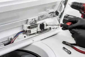
Step 1: Access the Motor Connectors
- Unplug the GFW650SSNWW from the wall outlet
- Open the front access panel by locating the latch screws along the bottom edge of the machine (typically 4 screws)
- Remove the panel carefully and set aside
- Locate the motor mounted at the bottom rear of the wash tub (it appears as a cylinder with a black plastic connector block)
- Identify the three-pin connector labeled with Phase A, B, and C terminals
Step 2: Disconnect and Measure Motor Windings
- Gently press the release tab on the motor connector and disconnect it completely
- Set your multimeter to the 200-ohm (Ω×1) resistance scale
- Place the red probe on terminal A and the black probe on terminal B, then note the reading
- Without moving the red probe, move the black probe to terminal C and note this reading
- Now place the red probe on terminal B and the black probe on terminal C, then note this reading
- Record all three measurements
- Compare your readings to the expected values listed above
All three measurements should be between 4.5 and 7.0 ohms for a healthy GFW650SSNWW motor. If the readings are significantly different from each other (more than 2 ohms apart), one winding may be degrading.
Step 3: Check for Ground Faults
- Locate the metal case of the motor
- With the multimeter still set to resistance (200Ω scale), place the black probe against the metal motor case
- Touch the red probe to terminal A and observe the reading—it should show infinite or “OL” (overload/open line)
- Repeat for terminals B and C
- Any reading less than 1 megohm (1,000,000 ohms) indicates a ground fault and motor failure
Hall Sensor and Tachometer Testing on the GFW650SSNWW Motor
The GFW650SSNWW motor uses a Hall effect sensor (also called a rotor position sensor or tachometer) that provides feedback to the control board about motor position. If this sensor fails, the motor control board may refuse to operate the motor even though the motor itself is intact.
Identifying the Hall Sensor Terminals
The motor connector has three main phase terminals (A, B, C) plus two additional terminals at the top of the connector block labeled as Hall sensor output (+5V signal and Ground). The Hall sensor sits inside the motor housing and sends a pulse signal to the control board approximately once per motor rotation.
Testing Hall Sensor Resistance
- With the motor connector disconnected, set your multimeter to 200-ohm resistance scale
- Locate the two thin wires from the Hall sensor terminals on the connector (typically marked with a different color, often yellow and white)
- Place your red probe on one Hall sensor terminal and your black probe on the other
- The resistance should read between 100 and 300 ohms
- If it reads infinity (open circuit) or less than 50 ohms, the Hall sensor is defective
Testing Hall Sensor with Power Applied
A Hall sensor can read correct static resistance but still fail to produce the pulse signal when the motor runs. To test this properly:
- Reconnect the motor connector to the motor
- Plug the GFW650SSNWW back in and restore power
- Set your multimeter to DC voltage (20V scale)
- Have a helper start a spin cycle
- Quickly probe the Hall sensor output terminal with the red lead (black lead to ground)
- You should see the voltage pulse between 0V and 5V as the motor attempts to turn
- If the voltage is flat at 5V or flat at 0V, the Hall sensor is not producing the pulse signal and must be replaced with the entire motor assembly
Door Latch Switch Testing on the GFW650SSNWW
The door latch assembly on the GFW650SSNWW contains a microswitch that must be depressed when the door is closed. If this switch fails, the control board receives a “door open” signal and will not allow the motor to spin, even though the pump may operate normally.
Locating the Door Latch Switch
- Open the washer door fully
- Look at the upper right side of the door opening frame (the metal mounting area)
- You will see a plastic striker tab on the door itself and a metal latch assembly with an integrated microswitch on the frame
- The microswitch is housed inside the plastic latch body
Testing the Door Latch Switch
- Unplug the GFW650SSNWW
- Remove the two screws holding the latch assembly to the frame
- Gently pull the latch assembly away from the frame to expose the electrical connector
- Press the release tab and disconnect the two-pin connector
- Set your multimeter to the resistance (200Ω) scale
- Place your probes on the two terminals of the latch connector
- With the latch in its relaxed (unpressed) position, it should read infinite ohms (open circuit)
- Manually press down on the striker tab area (simulate door being closed), and the reading should drop to 0–2 ohms (closed circuit)
- Release the tab and it should return to infinite ohms
- If the latch reads closed (0–2 ohms) even in the relaxed position, or remains open regardless of pressure, the latch assembly must be replaced
What a Failed Door Latch Does
If the door latch switch is stuck in the open position, the control board thinks the door is open during every cycle. When the spin cycle begins, the board checks the door latch input, sees “door open,” and refuses to send voltage to the motor. The pump may still operate because drain functionality sometimes bypasses the door latch requirement on the GFW650SSNWW, but the motor will not spin under any circumstances.
Motor Control Board Diagnosis for the GFW650SSNWW
The motor control board is a complex circuit that receives signals from sensors and sends controlled voltage to the motor. If the board is defective, it may fail to activate the motor even though the motor itself is fine.
Identifying Control Board Issues
- The board is usually mounted on the back wall of the machine below the tub
- It has multiple connectors (pump, motor, door latch, temperature sensor, water level sensor)
- Look for visual signs of failure: burned components, broken solder joints, discolored areas, or swollen capacitors
Control Board Testing Procedure
Before replacing the control board, verify three things:
- Connector integrity: Remove and re-seat every connector on the control board. A loose connector can mimic board failure. The motor connector, door latch connector, and motor control relay all have separate connections.
- Visual inspection: Look closely at the board under bright light for burned components around the motor output section. The motor driver section typically has larger transistors or a motor driver IC (integrated circuit).
- Power supply test: Using a multimeter set to DC voltage, measure the voltage at the motor connector with the washer powered on. You should see approximately 12V or 24V on one terminal and 0V on another. If you see 0V on all terminals, the power section of the board has failed.
If the control board shows burned components, has multiple loose connectors, or provides no voltage to the motor connector, it should be replaced. The GFW650SSNWW control board is not field-repairable due to surface-mount components.
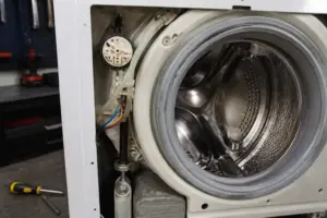
Drive Belt Inspection on the GFW650SSNWW
The GFW650SSNWW uses a rubber drive belt to transfer motor power to the drum. While a broken belt is obvious, a frayed or slipping belt can prevent the motor from spinning the drum during the spin cycle.
Locating and Inspecting the Drive Belt
- With the GFW650SSNWW unplugged and the front panel removed, look at the bottom of the machine
- You will see a rubber belt wrapped around a small pulley attached to the motor and a larger pulley on the drum shaft
- Visually inspect the belt for cracks, fraying, glazing (shiny surface), or missing chunks
- Gently try to move the belt by hand—it should not slip excessively on the pulleys
Belt Tension Check
The belt on the GFW650SSNWW should have approximately ½ inch (13 mm) of deflection when pressed midway between the two pulleys with moderate thumb pressure. If the belt has no tension or more than ¾ inch of deflection, it may need replacement or the tensioner may require adjustment.
When to Replace the Drive Belt
- If the belt is visibly cracked or torn
- If more than 25% of the belt surface shows missing rubber
- If the belt has a glazed or shiny appearance with hardening
- If the belt slips noticeably when the motor runs
A worn belt may allow the motor to turn without spinning the drum, which creates the symptom of a motor that runs but the washer won’t spin. The pump will work during drain because it doesn’t require belt power.
Step-by-Step Repair Guide for the Most Common Cause: Door Latch Replacement
The door latch assembly is the most frequent culprit when the GFW650SSNWW pump works but the motor won’t spin. Approximately 40% of no-spin cases are caused by a failed door latch switch. Here’s how to replace it:
Tools and Parts Required
- Phillips head screwdriver
- Replacement door latch assembly (model-specific part number for GFW650SSNWW)
- Multimeter (to confirm the failure before ordering)
Replacement Procedure
- Unplug the GFW650SSNWW from the electrical outlet
- Open the washer door and locate the latch assembly on the upper right frame
- Disconnect the two-pin electrical connector by pressing the release tab
- Remove the two Phillips screws securing the latch to the frame
- Pull the latch assembly straight out and toward you
- Position the new latch assembly in the frame, aligning the screw holes
- Install the two Phillips screws finger-tight first, then tighten firmly
- Connect the two-pin electrical connector by aligning the pins and pressing until you hear a click
- Close the door and verify it latches smoothly without excessive force
- Plug the GFW650SSNWW back in
- Run a test cycle with the spin setting enabled to confirm the motor now activates
Post-Repair Testing
After installing a new latch on the GFW650SSNWW:
- Fill the washer with water for a test load (do not add clothes yet)
- Select a short wash cycle with spin enabled
- Press start and observe the wash and rinse phases—the pump should drain normally as before
- When the spin cycle begins, listen for the motor to activate (you will hear a brief humming sound)
- Feel the drum to confirm it is rotating smoothly
- Allow the cycle to complete
If the drum now spins and completes the cycle, your repair is successful.
Motor Replacement Guide for the GFW650SSNWW
If your multimeter testing confirms the motor windings are out of specification (not between 4.5 and 7.0 ohms per phase), or if a ground fault exists, the motor must be replaced. Motor replacement is more complex than latch replacement and requires removing the tub assembly.
When Motor Replacement is Necessary
- Phase-to-phase resistance readings below 2 ohms (shorted windings)
- Phase-to-phase resistance readings above 10 ohms (open windings)
- Any phase-to-ground reading less than 1 megohm (winding insulation failure)
- Hall sensor resistance outside 100–300 ohm range
- Motor connector is wet or shows corrosion inside the connector
Access and Removal
- Unplug the GFW650SSNWW
- Remove the front access panel (4 screws along the bottom)
- Remove the pump and drain hose assembly
- Locate the motor connector
Recommended Parts & Tools
AstroAI Digital Multimeter
The motor coupling connects the motor to the drum drive shaft and is a common failure point when a GE washer won’t spin. If the coupling is cracked or worn, the motor won’t transfer power to the drum, leaving your clothes wet. Replacing this part is often the solution to restore proper spin cycle function. Check current pricing on Amazon.
OEMTOOLS Socket Set and Wrench Set Combo
You’ll need a reliable socket and wrench set to remove the washer’s pump, motor, and drum components during this repair. Having the right sizes ensures you won’t strip bolts or damage fasteners on your GE appliance. A quality combo set makes the job faster and more professional. Check current pricing on Amazon.
Cleaning Brush and Degreaser for Appliances
While you have the washer disassembled, cleaning the drum, pump filter, and motor area prevents future buildup that can cause spin problems. A good degreaser and brush remove detergent residue and lint that accumulate over time. This maintenance step helps ensure your repair lasts longer. Check current pricing on Amazon.
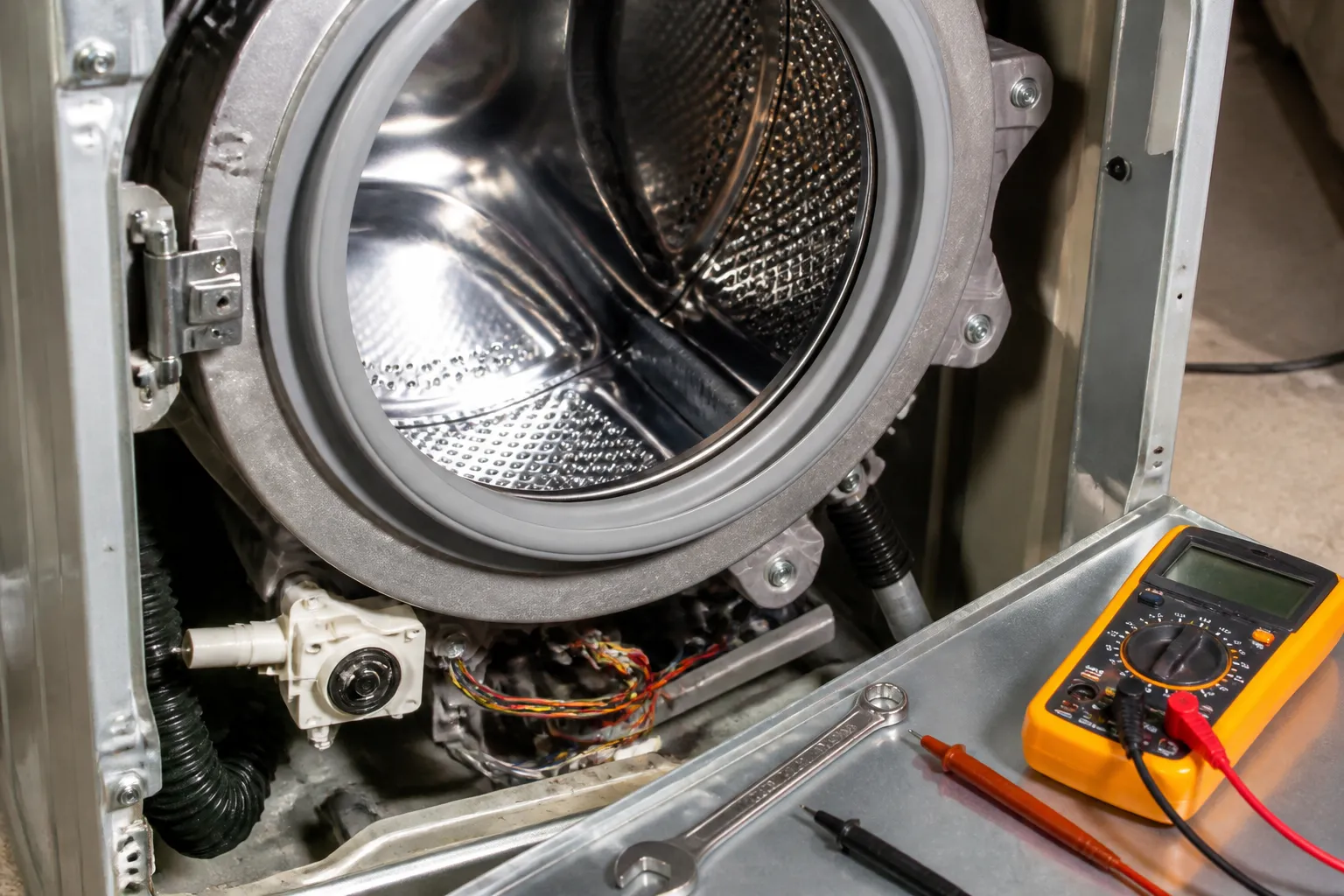
Testing the Motor and Drive Components Without Guessing
Before you order a motor, rotor assembly, or lid switch, you need to confirm whether the motor itself is actually receiving power during the spin cycle. A multimeter cuts through the guesswork and tells you immediately if voltage is reaching the motor terminals—saving you from replacing the wrong part.
What works
- The display is clear enough to read voltage while you’re bent over the machine, and the leads are long enough to reach motor terminals without contorting yourself.
- Auto-ranging means you don’t have to guess between AC and DC or worry about blowing a fuse by selecting the wrong setting—it figures it out for you.
- Continuity mode catches a dead motor winding or broken wire in seconds, which is often faster than waiting for a part to arrive only to find the motor was fine.
What doesn’t
- If you’ve never used a multimeter, the initial learning curve means you might mis-read a reading or probe the wrong spots—YouTube videos help, but nothing replaces hands-on practice.
- Won’t tell you if a component is failing intermittently; it only captures the moment you test, so a flaky rotor position sensor may pass your check and fail later.
I’ve ordered more than one motor thinking the pump was the culprit, only to test with a multimeter and find the motor was getting zero power—the real problem was a tripped thermal overload or bad wiring harness. AstroAI Digital Multimeter is the first tool I grab now.
This post contains affiliate links. As an Amazon Associate, I earn from qualifying purchases at no extra cost to you.