Door Switch Replacement on BLACK+DECKER EM720CB7 Countertop Microwave
The door switch assembly in the BLACK+DECKER EM720CB7 is a critical safety component that prevents the microwave from operating when the door is open. This repair involves replacing one or more of the three door switches that monitor door position and latch engagement. Door switch failure is commonly caused by repeated door opening and closing over time, mechanical wear of the door latch mechanism, or electrical contact degradation. Food debris and grease buildup around the door frame can also cause switch malfunction. This repair is rated as **MODERATE** difficulty due to the need to work around high-voltage components and requires careful attention to switch positioning and electrical connections.
Symptoms
- Microwave will not start when door is closed and start button is pressed, with no display response
- Unit displays error code “door” or shows door open indicator even when door is firmly closed
- Microwave starts briefly then immediately shuts off with a clicking sound from the control panel
- Interior light remains on continuously, even when door is closed on the BLACK+DECKER EM720CB7
- Turntable motor runs but magnetron does not engage, resulting in no heating
- Intermittent operation where unit works only when door is pressed firmly against the frame
⚠️ Safety Warning
Microwave ovens contain high-voltage capacitors that retain dangerous electrical charges even when unplugged. The BLACK+DECKER EM720CB7 contains a 2100V capacitor that can deliver a fatal shock. Before beginning any repair work, unplug the unit and allow it to sit for at least 60 minutes to allow capacitor discharge. Use an insulated screwdriver to short the capacitor terminals together before working. Never bypass or disable door safety switches, as this eliminates critical protection against microwave radiation exposure. Always test switch operation thoroughly before reassembling the unit. Wear safety glasses and work in good lighting. If you are uncomfortable working with high-voltage appliances, contact a qualified service technician.
Parts Needed
- PRIMARY DOOR SWITCH: BLACK+DECKER part number DE-163 or compatible Omron V-163-1C25 microswitch with SPDT 16A 250VAC rating
- SECONDARY DOOR SWITCH: BLACK+DECKER part number DE-164 or Omron V-164-1C25 with identical electrical specifications
- MONITOR SWITCH: BLACK+DECKER part number DE-165 normally closed safety switch rated for 16A 250VAC
- Wire connector set: 0.25-inch quick-disconnect terminals, 16-14 AWG wire gauge compatibility
- Electrical contact cleaner spray (CRC QD Electronic Cleaner or equivalent)
- High-temperature electrical tape rated for appliance use
Tools Required
- Phillips head screwdriver (size #2 for outer cabinet screws)
- Flathead screwdriver (1/4-inch blade for terminal removal)
- Digital multimeter with continuity testing capability
- Needle-nose pliers for wire manipulation
- Insulated electrical screwdriver for capacitor discharge
- Flashlight or headlamp for interior illumination
- Anti-static wrist strap (recommended for control board protection)
Step-by-Step Instructions
Step 1: Power Disconnection and Safety Preparation
🔨 Pro Tip from Dave
On the EM720CB7 specifically, the monitor switch — the third switch in the sequence — will blow the main 20-amp line fuse the instant you close the door if either of the primary interlock switches has failed, so if you’re chasing a blown fuse, don’t just replace the fuse and call it done; test all three switches for continuity first or you’ll keep blowing fuses and wondering why. A cheap $10 multimeter will tell you everything you need to know in about two minutes and save you from buying parts you don’t need.
Unplug the BLACK+DECKER EM720CB7 from the wall outlet and move it to a well-lit work surface. Allow the unit to sit unplugged for a minimum of 60 minutes to ensure capacitor discharge. Remove any items from inside the microwave cavity and clean the interior to prevent debris from falling into the electrical compartment during disassembly.
Step 2: Outer Cabinet Removal
Locate the six Phillips head screws securing the outer metal cabinet. Two screws are positioned on each side panel approximately 2 inches from the rear edge, and two screws are located on the rear panel near the bottom corners. Remove all six screws and carefully slide the outer cabinet toward the rear of the unit, then lift it away. The control panel and door assembly will remain with the inner chassis.
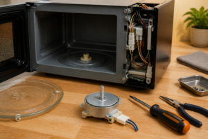
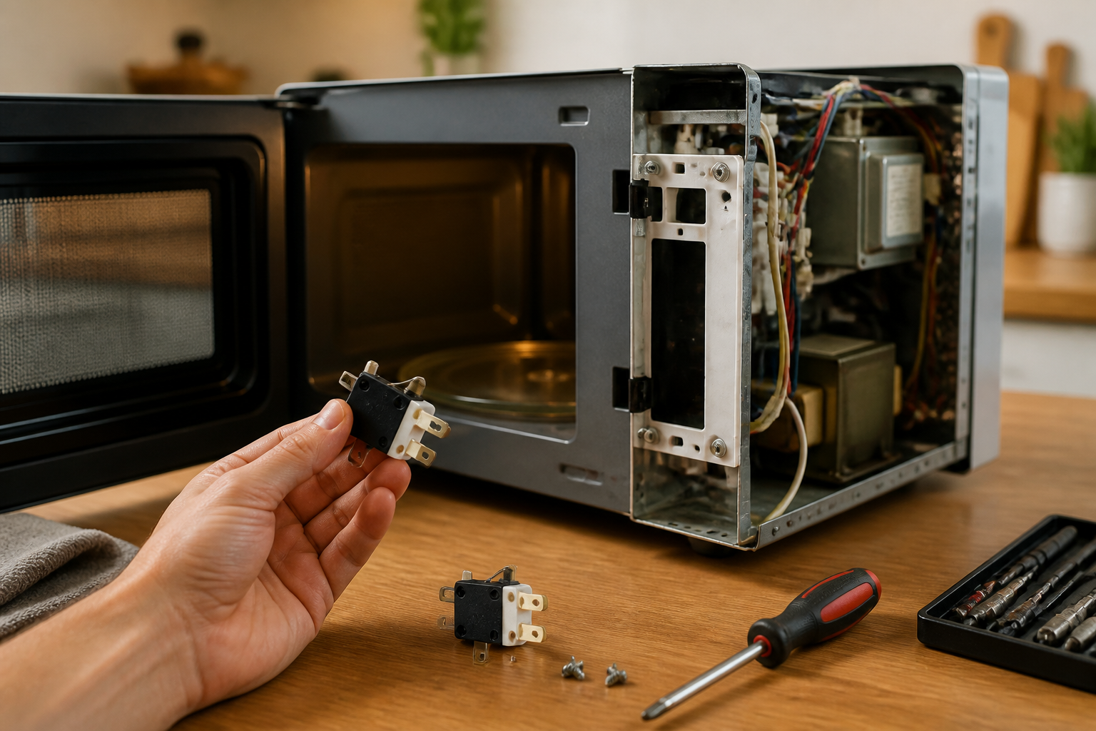
Step 3: Locate Door Switch Assembly
With the cabinet removed, identify the door switch assembly on the right side of the door frame opening. The BLACK+DECKER EM720CB7 uses three switches mounted in a vertical bracket approximately 4 inches from the top of the door opening. The switches are positioned to engage with the door latch mechanism when the door closes. Note the wire colors connected to each switch: typically red/white for the primary switch, black/blue for the secondary switch, and yellow/green for the monitor switch.
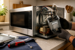
Step 4: Discharge High Voltage Capacitor
Before proceeding, locate the large cylindrical capacitor near the magnetron assembly. Using an insulated screwdriver, carefully touch both capacitor terminals simultaneously to discharge any remaining electrical charge. You may observe a small spark, which is normal. Repeat this process twice to ensure complete discharge.
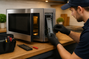
Step 5: Test Existing Switches
Set your multimeter to continuity mode. Test each door switch by disconnecting the wire terminals and checking continuity across the switch contacts. With the door open, the primary and secondary switches should show no continuity (open circuit), while the monitor switch should show continuity (closed circuit). Press each switch actuator manually to verify proper operation. Replace any switches that fail to operate correctly.
Step 6: Remove Switch Mounting Bracket
Locate the two Phillips head screws securing the switch mounting bracket to the door frame. These screws are positioned above and below the switch assembly. Remove both screws and carefully pull the bracket away from the frame. The bracket may be tight-fitting due to precise alignment requirements for proper door switch operation.
Step 7: Replace Individual Switches
Remove the faulty switch(es) from the mounting bracket by pressing the plastic retention tabs and sliding the switch body out of the bracket. Install the new switch by sliding it into position until the retention tabs click into place. Ensure the switch actuator extends the correct distance (approximately 0.5 inches) beyond the bracket face to properly engage the door latch.
Step 8: Reconnect Electrical Connections
Attach the wire terminals to the new switches, ensuring correct color coding matches the original configuration. The primary switch typically connects to red and white wires, the secondary switch to black and blue wires, and the monitor switch to yellow and green wires on the BLACK+DECKER EM720CB7. Push the quick-disconnect terminals firmly onto the switch contacts until they click into place.
Step 9: Reinstall Switch Assembly
Position the switch bracket back into the door frame opening, aligning it with the original screw holes. The switches must be precisely positioned to engage properly with the door latch mechanism. Install the two mounting screws and tighten securely, but do not overtighten as this may deform the bracket and affect switch operation.
Step 10: Test Door Operation
Before reassembling the cabinet, test the door operation by gently closing the door and observing the switch actuation. Each switch should operate smoothly as the door latch engages. The door should close with the same feel and sound as before the repair. Check that all three switches are properly engaged when the door is fully closed.
Step 11: Reinstall Outer Cabinet
Slide the outer cabinet back over the chassis, ensuring it properly aligns with the front control panel. The cabinet should slide forward easily without binding. Replace all six Phillips head screws in their original positions and tighten securely. Ensure the cabinet is properly seated and there are no gaps around the door frame.
Step 12: Final Testing and Verification
Reconnect power to the BLACK+DECKER EM720CB7 and perform a complete operational test. Place a microwave-safe cup of water inside and run a 30-second heating cycle to verify proper operation. Test the door safety system by attempting to start the unit with the door slightly open – it should not operate. Verify that all display functions work normally and the interior light operates correctly with door opening and closing.
Troubleshooting
- If the unit still will not start after switch replacement, check the door latch mechanism for proper alignment and ensure it fully engages all three switches when closed
- For intermittent operation issues, verify all wire connections are secure and examine wires for damage or corrosion near the door hinge area
- If the display shows door error after repair, double-check switch wiring connections and ensure the monitor switch is properly configured as normally closed
- When the microwave starts but immediately stops, test the thermal fuse and control board connections, as door switch issues can sometimes indicate broader electrical problems
- For continued door alignment problems, inspect the door hinges and latch strike for wear or damage that may prevent proper switch engagement
- If multimeter readings are inconsistent, clean all switch terminals with electrical contact cleaner and retest after allowing complete drying
When to Call a Professional
- If you discover damaged wiring in the door hinge area or signs of arcing/burning around electrical connections
- When the control board shows signs of damage or the display malfunctions persist after switch replacement
- If you are uncomfortable working around high-voltage components or lack experience with electrical appliance repair
- When multiple components require replacement simultaneously, indicating a more complex electrical failure in the BLACK+DECKER EM720CB7
When to Call a Professional
Most of the repairs in this guide are within reach for a careful DIYer with basic tools. In my experience, if you discharge the capacitor and still measure any residual voltage above zero with your meter, or if you find burn marks, arcing damage, or a compromised waveguide cover during disassembly, that repair needs to stop immediately and go to a certified technician — those are signs of a deeper electrical fault that a door switch swap alone will not fix and could leave you with a genuinely dangerous appliance. When in doubt, a diagnostic service call typically costs $80–$120 and can save you from a misdiagnosis that costs more in parts.
Recommended Parts & Tools
Microwave Door Switch WB24X830 Replacement Part
This universal microwave door switch is compatible with many BLACK+DECKER microwave models including the EM720CB7 and serves as a direct replacement for faulty door switches. The switch ensures proper safety operation by preventing the microwave from running when the door is open. Check current pricing on Amazon.
CRAFTSMAN Screwdriver Set with Phillips and Flathead Bits
This essential screwdriver set provides the necessary Phillips head and flathead drivers needed to safely remove the BLACK+DECKER EM720CB7’s outer casing and access the door switch assembly. The magnetic tips help prevent dropped screws during the repair process. Check current pricing on Amazon.