🔩 Smart Board/Wi-Fi Module Repair Guide for LG LRE3193ST (Electric Range)
💡 This repair guide will be expanded with detailed instructions. Claude AI will add comprehensive explanations, safety tips, troubleshooting advice, and product recommendations.
🔨 Pro Tip from Dave
One thing that trips up a lot of DIYers on the LG LRE3193ST is forgetting to perform a full factory reset on the ThinQ app and unpair the range before installing the new EBR87157806 smart board — skipping this step will leave you scratching your head when the new board still won’t connect. Also, inspect the ribbon cable connector carefully before ordering parts, because a loose connection mimics a dead module almost perfectly.
🔍 Symptoms
Wi-Fi not connecting, smart features not working
🔧 Part Numbers
- EBR87157806
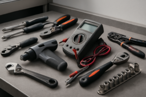
🔧 Required Tools
✔️ Difficulty & Cost
Difficulty: Moderate
Estimated Cost: $50-100
✔️ Repair Steps
Step 1: Disconnect power
Disconnect Power
1. Locate your home’s electrical service panel (breaker box), typically found in the basement, garage, utility room, or exterior wall of your home.
2. Open the breaker panel door by lifting or swinging it open.
3. Find the dedicated 240-volt double-pole breaker for your electric range. This will be a larger breaker taking up two slots, typically labeled “Range,” “Stove,” or “Kitchen Appliance,” and rated at 40 or 50 amps.
4. Flip both switches of the double-pole breaker to the OFF position. Both handles should move together as they’re connected by a bridge—push them fully to the opposite side until they click into place.
5. Return to the range and verify power is disconnected by attempting to turn on a burner using the control panel. The display should be completely dark with no lights, sounds, or response.
6. Pull the range away from the wall approximately 24-36 inches to access the rear panel. Grip the range from both sides at the front and pull straight out—LG ranges typically have adjustable leveling legs that may scrape slightly on the floor.
7. Look at the lower rear section of the range, approximately 8-10 inches from the bottom and centered horizontally. You’ll see either a hardwired connection through a strain relief connector or a range power cord plugged into a wall outlet.
8. **For plug-in connections**: Grasp the large plug body (not the cord) where it connects to the wall receptacle and pull straight out with firm, steady pressure. The plug is heavy—support it with both hands to prevent it from falling and damaging the prongs.
9. **For hardwired connections**: Remove the junction box cover plate (typically held by one or two Phillips-head screws #2) located at the lower rear center of the range. Inside you’ll see 4 wires: two hot wires (typically red and black), one white neutral wire, and one bare copper or green ground wire connected to wire nuts or terminal blocks.
10. Place a non-contact voltage tester against each exposed wire terminal or wire nut to confirm zero voltage. The tester should not light up or beep for any wire.
Troubleshooting Tips for This Step
**If the breaker isn’t labeled**: Turn off breakers one at a time and check if the range display goes dark. Mark the correct breaker with a label for future reference.
**If the plug won’t release from the wall outlet**: Rock the plug gently side-to-side while pulling—don’t yank, as this can damage the outlet or prongs. These 240-volt plugs fit very snugly due to their amperage rating.
**If you accidentally touch wires in a hardwired setup**: Stop immediately, verify the breaker is OFF using the voltage tester on each wire, then proceed only after confirming zero voltage on all conductors.
**If the range is too heavy to pull**: Empty the oven and all drawers to reduce weight, or have a second person assist with pulling while you guide from the side.
Step 2: Remove lower back panel
Remove Lower Back Panel
1. Locate the lower back panel, which covers the bottom third of the range’s rear surface, extending from the floor to approximately 18 inches up from the base.
2. Identify the 6 Phillips-head screws securing the lower back panel: 4 screws along the top edge (spaced approximately 8 inches apart) and 2 screws on the left and right sides (positioned 6 inches from the bottom edge).
3. Using a Phillips-head #2 screwdriver, remove the 4 top-edge screws first, turning counterclockwise. Place screws in a container to prevent loss.
4. Remove the 2 side screws using the same screwdriver, turning counterclockwise.
5. Grip the panel at the bottom center and pull it straight back approximately 1 inch. The panel has two metal tabs at the bottom that hook into slots on the frame.
6. Lift the panel upward 2 inches to disengage the bottom tabs from their slots, then pull the panel completely away from the range.
7. Set the panel aside in a safe location where it won’t be stepped on or bent.
8. Look inside the opening—you’ll see a wire harness bundle containing approximately 8-12 wires in various colors (typically black, white, red, blue, yellow, and green) running vertically along the left side of the cavity, approximately 4 inches from the left edge.
9. Examine the wire bundle—it may be secured with 1-2 plastic zip ties or wire clips attached to metal mounting tabs on the frame.
10. Using wire cutters or scissors, cut any zip ties holding the wire bundle. Do not pull on the wires themselves; cut only the plastic ties.
11. Gently push the wire bundle 2-3 inches to the left, away from the center access area, to create clearance for accessing the smart board in the next steps.
Troubleshooting Tips for This Step
**If screws are stuck or won’t turn:** – Apply penetrating oil (WD-40) to the screw head and wait 5 minutes before attempting removal again. – Ensure your screwdriver is fully seated in the screw head to prevent stripping. – If a screw is stripped, use a screw extractor bit sized for #8 screws.
**If the panel won’t come off after removing screws:** – The bottom tabs may be corroded or stuck. Rock the panel gently side-to-side while pulling outward. – Check for any missed screws—count again to verify all 6 screws are removed. – Inspect the top edge for any clips that may have caught on the frame edge; slide a flat-head screwdriver along the top to release.
**If wires are under tension or appear stretched:** – Stop pulling immediately. Trace the wire bundle upward to locate where it connects—there may be an intermediate connector 12-18 inches above the opening that’s catching. – Push slack wire down from above to create more working room below.
**If a wire becomes disconnected accidentally:** – Note the wire color and trace it to its origin point—connectors typically have matching colored terminals or labeled positions. – Most connectors in this area are push-on spade terminals that simply press onto metal tabs until they click and seat firmly.
Step 3: Locate Wi-Fi module
Locate Wi-Fi Module
1. Look at the rear wall of the range cavity (the open area behind where the control panel was). The Wi-Fi module is a small black rectangular box measuring approximately 2 inches wide by 3 inches long by 1 inch deep.
2. Locate the module positioned on the right side of the cavity, mounted approximately 8-10 inches down from the top edge and 3-4 inches in from the right side wall.
3. Identify the module by its distinctive features: it has a small black antenna wire (approximately 4 inches long) extending from one end, and a single white 6-pin connector plug attached to it with a wire harness containing white, black, red, yellow, blue, and green wires.
4. Check if a metal shield or bracket partially covers the module. This is a thin metal plate held by 2 Phillips-head screws. If present, remove these screws using a Phillips-head #2 screwdriver and set the shield aside.
5. Examine the wire harness leading to the module. You’ll see it runs from the module toward the left side, where it connects to the main control board. The harness may be secured with 1-2 plastic zip ties along its path.
6. Verify you’ve found the correct module by looking for the FCC ID label on its surface, which reads “FCC ID: BEJLGPCR” or similar LG identification numbers.
Troubleshooting Tips for This Step
**If you cannot locate the module in the described position:** – Check the left side of the cavity mirror position (8-10 inches down, 3-4 inches from left edge) as some production variations place it there. – Look for the distinctive black antenna wire, which is the easiest identifier. – Trace the wire harness backward from the main control board (large circuit board on the left side) until you find a small black box with 6 wires terminating at it.
**If the module appears different from the description:** – Confirm you’re looking at a box with an antenna wire, not the temperature sensor (which is cylindrical and has only 2 wires, both white or red). – The Wi-Fi module will always have 4-6 wires in its connector, never just 2.
**If wires are blocking your view:** – Push the main wire harness bundle (thick group of wires running vertically along the right side) approximately 2 inches to the left. This will expose the module mounting area. – Do not pull wires; only push the bundle as a group to avoid disconnecting anything prematurely.
**If you see multiple small black boxes:** – The Wi-Fi module is the only component with an external antenna wire visible. – Other small black boxes without antennas are likely relay modules or capacitors, which have different connector types (typically 2-4 blade terminals instead of a white plastic plug connector).
Step 4: Disconnect wire harness
Disconnect Wire Harness
1. Locate the smart board/Wi-Fi module mounted on the left side of the control panel, approximately 3 inches from the top edge and 2 inches from the left edge.
2. Identify the main wire harness connector attached to the smart board—it’s a white rectangular plug approximately 1 inch wide with a gray locking tab on top.
3. Press down firmly on the gray locking tab with your thumb while pulling the connector straight away from the board with your other hand. You’ll feel the tab click down about 1/8 inch before the connector releases.
4. Pull the white connector straight back approximately 2 inches until it completely separates from the smart board. Do not twist or rock the connector—pull in a single straight motion to avoid bending the pins.
5. Examine the connector you just removed. You’ll see 6 wires entering the back: two white wires, one black wire, one red wire, one blue wire, and one green wire. The wire positions from left to right are: white (neutral), black (hot), red (hot secondary), blue (data), white (neutral secondary), green (ground).
6. Move the disconnected harness 4-6 inches to the left and drape it over the metal frame rail to keep it out of your work area.
7. Locate the secondary antenna wire connection on the right side of the smart board—it’s a small gold coaxial connector approximately 1/4 inch in diameter with a black wire attached.
8. Grip the gold metal connector (not the black wire) between your thumb and index finger.
9. Pull the gold connector straight away from the board with steady pressure. It requires approximately 3-5 pounds of force to disconnect and will release suddenly, so maintain control.
10. Check that both connectors are now completely free from the smart board. The board should have no wires attached at this point.
Troubleshooting: If Wires Become Disconnected
**If individual wires pull out of the white connector during disconnection:** – Match wire colors to the terminal positions: white wires go to positions 1 and 5, black to position 2, red to position 3, blue to position 4, green to position 6 – Insert the wire straight into the terminal opening until you hear a click – Tug each wire with 2-3 pounds of force—it should not pull free if properly seated
**Verification of complete disconnection:** – The smart board should move freely when gently wiggled—no wire tension should restrict movement – Both the white connector and gold antenna connector should be hanging loose – Count that all 6 wires in the main harness are still inserted in the white connector (none pulled out during removal)
**Common mistake:** – Never pull on the wires themselves when disconnecting—always grip the connector body or the locking tab. Pulling wires can extract them from the connector terminals, requiring individual wire reinsertion using the color/position guide above.
Step 5: Remove mounting screws
Remove Mounting Screws
Locating and Removing the Smart Board Mounting Screws
1. Identify the two Phillips-head mounting screws holding the smart board/Wi-Fi module to the control panel bracket—one screw is located at the top-left corner of the module, approximately 1 inch from the left edge, and the second screw is at the top-right corner, approximately 1 inch from the right edge.
2. Notice the white wire harness running diagonally across the left mounting screw—this is the power supply connector with 3 wires (red, white, and black) that may partially block your screwdriver access.
3. Push the white wire harness gently upward and to the left, creating approximately 1 inch of clearance above the left mounting screw, then hold it in place temporarily by tucking it behind the metal bracket lip.
4. Insert your Phillips #2 screwdriver into the left mounting screw at a 90-degree angle to the board surface—the screw is approximately 1/2 inch long with a silver finish.
5. Turn the screwdriver counterclockwise 8-10 full rotations until the screw is completely free from the mounting bracket—the screw will remain partially in the board’s mounting hole but will no longer grip the bracket.
6. Remove the screw completely from the mounting hole and place it in a small container—the screw head diameter is approximately 1/4 inch.
7. Move to the right mounting screw, which should have unobstructed access, and insert your Phillips #2 screwdriver at a 90-degree angle.
8. Turn counterclockwise 8-10 full rotations until this screw is completely free, then remove it and place it with the first screw.
9. Grasp the smart board module on both sides, holding the left and right edges simultaneously—the board will now be loose but still connected by the wire harness you moved earlier.
10. Gently pull the board forward approximately 1/4 inch away from the mounting bracket to create clearance for the next step (disconnecting the wire harness).
Troubleshooting Tips for This Step
**If screws won’t turn:** The screws may have threadlocker compound applied—apply firm downward pressure while turning to break the seal. If the screwdriver slips, the screw head may be partially stripped; switch to a Phillips #3 screwdriver for better grip.
**If the wire harness snaps back into position:** Use a small zip tie or twist tie to temporarily secure the wire bundle to the metal bracket frame on the left side, keeping it 1-2 inches away from the screw location.
**If a screw falls into the control panel cavity:** Tilt the range slightly backward (10-15 degrees) and shake gently to retrieve the screw from the bottom edge of the cavity, or use a magnetic pickup tool to retrieve it.
**If the board doesn’t pull forward after screw removal:** Check that both screws are completely removed—sometimes the right screw can hide behind a small metal tab and appears removed but still has 1-2 threads engaged.
**Module movement verification:** After removing both screws, the smart board should move freely forward and backward by approximately 1/4 inch with light finger pressure—if it doesn’t move, recheck that both mounting screws are fully removed.
Step 6: Install new module
Install New Smart Board/Wi-Fi Module
1. Remove the new smart board/Wi-Fi module from its anti-static packaging by holding it by the edges only, avoiding contact with any metal contacts or circuit traces on the green board surface.
2. Orient the new module so the antenna connector (round silver metal cylinder approximately 3/8 inch diameter) faces toward the back of the range and the white wire connector port faces downward.
3. Align the two mounting screw holes on the module (located at the top left and top right corners, approximately 3 inches apart) with the threaded standoffs or holes on the control board mounting bracket.
4. Insert the module at a 30-degree angle, sliding the bottom edge into the retaining clip or slot located at the base of the mounting bracket (approximately 1/2 inch from the bottom edge).
5. Press the top of the module firmly until it sits flush against the mounting surface – you should feel no gap between the module and the bracket.
6. Locate the white 6-pin wire connector you disconnected earlier (it has 6 individual wires: typically red, black, white, blue, yellow, and green). Hold the connector with the locking tab facing up.
7. Align the connector with the matching white port on the bottom of the new module – the connector is keyed and will only fit one way, with the wider side matching the wider opening.
8. Push the connector straight into the port until you hear and feel a distinct click – the connector should be fully seated with no gap visible between the connector housing and the module port.
9. Verify the connection by gently pulling on the wire bundle (not individual wires) with approximately 2-3 pounds of force – the connector should not pull out.
10. Reconnect the antenna cable (black coaxial wire with silver metal tip) to the round antenna port by pushing straight down until you hear a click – the metal collar should be flush with the connector base.
11. Install the two Phillips-head screws (the ones you removed in Step 2) through the mounting holes at the top corners of the module, threading them clockwise by hand first.
12. Tighten the screws using a Phillips #2 screwdriver in a clockwise direction until snug – apply firm pressure but stop when the module is secure against the bracket (approximately 6-8 inch-pounds of torque, similar to tightening a light switch cover plate).
Troubleshooting This Step:
**If the wire connector won’t seat fully:** Rotate the connector 180 degrees – you may have it upside down. The keyed design prevents incorrect installation, but the connector must align precisely.
**If wires pulled loose from the connector:** Match wire colors to the terminal positions visible through the clear connector housing. From left to right (viewing from the locking tab side), typical order is: green (ground), white (neutral), red (line 1), black (line 2), blue (communication), yellow (communication).
**If the antenna connector won’t click:** The center pin may be misaligned. Pull the connector off, ensure the small brass center pin inside the port is straight and centered, then retry the connection with straight downward pressure.
📝 Next Steps: This post will be expanded by Claude AI with:
- Detailed step-by-step instructions with explanations
- Safety warnings and precautions
- Tool recommendations and usage tips
- Troubleshooting common issues
- Product recommendations (repair kits, tools) from Amazon via Firecrawl
- Affiliate links integrated naturally into sentence form
🔧 Recommended Parts & Tools
You can find the replacement part you need, such as this 86” Smart Board, 4K Touch Screen Interactive Whiteboard Display, AI Camera w…, on Amazon. For this repair, you’ll need a ELEGOO Upgraded 37 in 1 Sensor Modules Kit with Tutorial Compatible with R3 M… which includes all the necessary components. You can find the replacement part you need, such as this CoreCentric Remanufactured Refrigerator Control Board Replacement for LG EBR8…, on Amazon. You can find the replacement part you need, such as this LG EAT61976201 Module, Bluetooth, on Amazon.
As an Amazon Associate, I earn from qualifying purchases.
How Much Does This Repair Cost?
Replacement smart board EBR87157806 typically runs $55–$90 through online parts suppliers for a DIY repair. A professional technician will charge an additional $80–$150 in labor, bringing your total to roughly $135–$240 depending on your area.
Recommended Products
These are the parts and tools we recommend for this repair, based on compatibility and customer reviews:
- CoreCentric Remanufactured Dishwasher Electronic Control Board Replacement for LG ebr79609805
- CoreCentric Remanufactured Laundry Dryer Electronic Control Board Replacement for LG EBR76542911
- EATAKWARD EBR74164805 Range Oven Relay Control Board, Replacement for LG LRE3021ST LRE3083SW LRE3083ST LRE6321ST Stove Oven
- EBR74164805 Range Oven Relay Control Board Replacement for LG Range/Stove/Oven Replaces LRE3021ST, LRE3083SW, LRE3833ST, LRE6321ST, LRE6383BD, LRE6383 SB, LRE6-383ST, LRE6383SW,etc.
As an Amazon Associate, I earn from qualifying purchases.