🔩 Oven Control Board (ERC) Repair Guide for Whirlpool WFE505W0HS (Electric Range)
💡 This repair guide will be expanded with detailed instructions. Claude AI will add comprehensive explanations, safety tips, troubleshooting advice, and product recommendations.
🔨 Pro Tip from Dave
When replacing the ERC on the WFE505W0HS, double-check whether your unit takes W11114647 or the older W10340939 — installers often order the wrong one and waste a week on returns. The ribbon cable connector on the display board is extremely fragile on this model; I’ve seen techs crack it just by pulling at the wrong angle, so always slide the locking tab sideways before pulling. Also photograph every wire harness position before disconnecting anything.
🔍 Symptoms
No display, error codes, oven won’t heat
🔧 Part Numbers
- W11114647
- W10340939
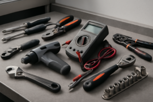
🔧 Required Tools
- 1/4″ nut driver
- Phillips screwdriver
- needle-nose pliers
✔️ Difficulty & Cost
Difficulty: Moderate-Difficult
Estimated Cost: $150-250
✔️ Repair Steps
Step 1: Disconnect power
1. Locate the circuit breaker panel in your home (typically mounted on a wall in the basement, garage, or utility room).
2. Open the circuit breaker panel door by lifting the latch or pulling the handle.
3. Find the breaker labeled for your kitchen range or oven (commonly labeled “Range,” “Oven,” or “Kitchen Appliance” with a 40-50 amp rating).
4. Flip the double-pole breaker switch fully to the OFF position (it will move from the center or right position to the left position, away from the center bus bar).
5. Place a piece of masking tape or painter’s tape over the breaker switch in the OFF position.
6. Write “DO NOT TURN ON – REPAIR IN PROGRESS” on the tape using a permanent marker to prevent someone from restoring power while you’re working.
7. Walk back to the range location in your kitchen.
8. Press and hold the oven control panel’s power button or any display button for 3-5 seconds to verify the display remains completely dark and unresponsive (this confirms power is disconnected).
9. Move to the back of the range and grasp both sides of the unit firmly.
10. Pull the range straight out from the wall approximately 24-30 inches to access the rear panel and power connection point.
11. Look at the lower rear section of the range, approximately 6-8 inches from the bottom and centered horizontally, to locate the power cord connection point.
12. Use a flashlight to illuminate the area behind the range and identify the power cord (a thick black cable, approximately 1 inch in diameter with 3 or 4 heavy-gauge wires inside).
13. Trace the power cord from the range to where it connects to the wall outlet (a large 3-prong or 4-prong 240-volt receptacle, typically mounted 2-6 inches above the floor).
14. Firmly grasp the power cord plug (not the cord itself) where it connects to the wall receptacle.
15. Pull the plug straight out from the wall outlet using steady, firm pressure until it completely separates from the receptacle.
16. Examine the prongs of the plug to confirm all 3 or 4 prongs are fully visible and clear of the outlet (this verifies complete disconnection).
17. Coil the power cord loosely and position it on top of the range or secure it away from your work area.
Step 2: Remove control panel screws
1. Open the oven door fully to provide access to the top edge of the range front panel where it meets the control panel.
2. Look at the top front edge of the range body, directly beneath where the control panel overhangs – you’ll see 2 Phillips-head screws positioned approximately 8 inches from each side edge of the range, securing the control panel to the cooktop frame.
3. Using a Phillips-head #2 screwdriver, rotate the left screw counterclockwise 8-10 full rotations until the screw comes free from the threaded hole – the screw length is approximately 1 inch.
4. Set this screw in a container immediately to prevent loss.
5. Using the same screwdriver, rotate the right screw counterclockwise 8-10 full rotations until it comes free.
6. Place this screw with the first one.
7. Close the oven door completely.
8. Stand directly in front of the control panel and locate 2 additional Phillips-head screws on the underside of the control panel lip – these screws are positioned approximately 10 inches from each side edge of the control panel, angling upward into the control panel housing.
9. Tilt your head to see underneath the control panel overhang clearly – you’ll see these screws threaded into the bottom edge of the control panel from below.
10. Using the Phillips-head #2 screwdriver, reach underneath the control panel lip and rotate the left screw counterclockwise 6-8 full rotations until it releases.
11. Add this screw to your container.
12. Rotate the right underside screw counterclockwise 6-8 full rotations until it releases.
13. Place this fourth screw with the others – you now have 4 total screws removed (2 from the top front edge, 2 from underneath the control panel).
14. Grip the control panel at both left and right edges with your hands positioned at the sides where the end caps meet the main panel.
15. Pull the entire control panel assembly forward and upward at a 45-degree angle approximately 2-3 inches – the panel will hinge away from the range back, remaining connected by wire harnesses behind it.
16. The control panel now hangs forward, exposing the wire connectors and the electronic control board mounted on the back of the panel.
Step 3: Take photo of wire connections
1. Position your smartphone or camera 8-10 inches directly above the control board, which is mounted at the upper rear of the range cavity behind the control panel you removed in Step 2.
2. Enable the flash on your camera device to illuminate the interior connections clearly.
3. Take your first overall photo capturing all wire harness connections attached to the control board, holding the camera parallel to the board surface.
4. Locate the large white multi-pin connector on the left side of the control board—this is the main power harness with 12 pins arranged in two rows.
5. Take a close-up photo of this white connector showing the wire colors entering it (you’ll see brown, orange, red, black, white, yellow, blue, and green wires).
6. Move to the center of the board and photograph the smaller 6-pin white connector located 3 inches right of the main connector—this controls the oven temperature sensor.
7. Locate the black 4-pin connector on the right side of the board, positioned 1 inch from the right edge—this connects to the display panel.
8. Take a close-up photo of this black connector, capturing the wire routing direction as the wires exit toward the front display panel.
9. Find the two individual spade terminals on the bottom right corner of the board (these are quick-disconnect terminals for the clock backup circuit).
10. Photograph these spade terminals, ensuring the wire colors (typically one brown, one blue) are clearly visible.
11. Check the back left area of the control board for a small 2-pin white connector if your model has a cooling fan—photograph this connection showing wire colors.
12. Review all photos on your camera screen, zooming in to verify that every wire color is identifiable and each connector’s orientation is clear.
13. Take one final wide-angle photo showing how all wire harnesses route from the control board down into the range body, capturing their paths and any securing clips.
14. Transfer these photos immediately to a second device (email them to yourself or save to cloud storage) to prevent accidental deletion during the repair process.
15. Keep your camera device nearby with photos readily accessible for reference during Step 5 (reinstallation).
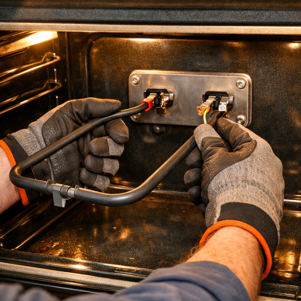
Step 4: Disconnect all wires (label them)
1. Locate the main wire harness connector on the right side of the control board, approximately 2 inches from the top edge—this is a white rectangular connector housing 12 wires.
2. Press the locking tab on the white connector downward with your thumb while pulling the connector body straight away from the board with your other hand—the connector will release with firm pressure of 3-5 pounds.
3. Find the smaller 6-wire connector located 3 inches below the main harness on the right side—this connector has a gray housing with red, white, blue, yellow, black, and green wires.
4. Squeeze the sides of the gray connector housing together between your thumb and forefinger, then pull straight out—you’ll feel it release after compressing approximately 1/8 inch.
5. Identify the oven temperature sensor connector at the bottom center of the control board—this is a 2-wire connector with a brown housing containing one red wire and one white wire.
6. Grip the brown connector body (not the wires) and pull straight away from the board—this connector has no locking tab and requires 2-3 pounds of pull force.
7. Locate the ground wire terminal on the left side of the control board, 1 inch from the bottom—this is a green wire attached with a single 1/4-inch hex head screw.
8. Use a 1/4-inch nut driver to turn the ground screw counterclockwise 4-5 complete rotations until the screw is free, then remove the ring terminal from the mounting post.
9. Create wire labels using masking tape and a permanent marker: Write “MAIN-12” on the white connector, “AUX-6” on the gray connector, “TEMP SENSOR” on the brown connector, and “GROUND” on the green wire.
10. Wrap each label around its respective connector or wire, leaving 1/2 inch of tape extending to press against itself for secure adhesion.
11. Bundle the disconnected wires together using a twist tie or cable tie, securing them 6 inches back from the connectors to prevent them from falling behind the range.
12. Verify all four connections are fully disconnected by gently tugging each wire harness—no resistance means successful disconnection—the control board should now have no wires attached to it.
Step 5: Remove mounting screws
1. Locate the four mounting screws securing the ERC control board to the rear panel of the range—you’ll find one screw in each corner of the control board, approximately 1 inch from each edge of the board’s perimeter.
2. Insert a ¼-inch hex nut driver into the top-left mounting screw (when facing the back of the board).
3. Rotate the nut driver counterclockwise 8-10 complete turns until the screw releases completely from the threaded standoff.
4. Pull the screw straight out and set it aside in your parts container.
5. Repeat this process for the top-right mounting screw—insert the ¼-inch hex nut driver and rotate counterclockwise 8-10 turns until free.
6. Remove the bottom-left mounting screw using the same technique—counterclockwise rotation with the ¼-inch hex nut driver.
7. Support the control board with your non-dominant hand by placing your palm against the front face of the board, applying light backward pressure to keep it against the rear panel.
8. While continuing to support the board with one hand, insert the ¼-inch hex nut driver into the final bottom-right mounting screw.
9. Rotate the driver counterclockwise 8-10 turns to remove this last screw—the board will now be free from the mounting panel but still connected by the wire harnesses you previously loosened.
10. Verify all four screws have been removed by visually inspecting each corner mounting hole—you should see the silver or brass-colored threaded standoffs protruding approximately ½-inch from the rear panel with no screws remaining in them.
11. Gently pull the control board forward approximately 2-3 inches away from the rear panel—the board should move freely without resistance from mounting hardware.
12. Inspect the four rubber or plastic standoff spacers (small cylindrical pieces approximately ¼-inch diameter) that may be positioned between the board and rear panel—these sometimes remain attached to the board and sometimes stay on the rear panel standoffs.
13. If the spacers are stuck to the board, leave them in place for now—you’ll transfer them to the new board during reinstallation.
14. The control board now hangs freely, supported only by the connected wire harnesses, ready for final wire harness removal in the next step.
Step 6: Install new board, reconnect wires
1. Position the new ERC board at the mounting bracket location on the right interior wall of the range, aligning the three mounting holes on the board with the corresponding holes in the metal bracket.
2. Insert the three 1/4-inch hex head screws through the mounting holes on the board into the bracket holes, threading them by hand first.
3. Using a 1/4-inch nut driver, tighten each screw in a star pattern: top screw first, then bottom left, then bottom right. Apply firm pressure until the board sits flush against the bracket with no gaps or movement.
4. Locate the largest wire harness connector (20-pin white rectangular connector, approximately 2 inches wide) on your new board, positioned at the bottom left corner of the board face.
5. Align the corresponding white 20-pin connector from the main wire harness with the board socket, matching the notch on the connector with the tab on the socket. Push firmly until you hear and feel two distinct clicks, indicating the locking tabs have engaged on both sides.
6. Connect the 6-pin connector (located 3 inches above the 20-pin connector) by aligning the connector’s ridge with the socket groove. Push straight in until it clicks and the connector sits flush with the board surface.
7. Attach the ribbon cable connector (flat gray cable, 1 inch wide) to the socket at the top right of the board. Insert the cable straight down into the horizontal socket slot until the white retention clips on both sides of the socket snap forward automatically, securing the cable.
8. Connect the temperature sensor wire (single white connector with two wires, red and white) to the socket labeled “SENSOR” at the center top of the board. Push until it clicks into place.
9. Connect the remaining 4-pin connector (if present on your model) to the socket at the bottom right corner of the board. This connector has a locking tab that faces upward; push until you hear a click.
10. Verify all five connections by gently pulling on each connector—none should release with light tugging force of approximately 2-3 pounds.
11. Visually inspect that no wires are pinched between the board and the bracket, and all wire harnesses hang naturally without sharp bends exceeding 90 degrees.
📝 Next Steps: This post will be expanded by Claude AI with:
- Detailed step-by-step instructions with explanations
- Safety warnings and precautions
- Tool recommendations and usage tips
- Troubleshooting common issues
- Product recommendations (repair kits, tools) from Amazon via Firecrawl
- Affiliate links integrated naturally into sentence form
🔧 Recommended Parts & Tools
You can find the replacement part you need, such as this 5304518660 for Electrolux Frigidaire Range Oven Control Board Timer ERC, on Amazon. For this repair, you’ll need a Genuine Oven Control Board 164D4105P021 Same Day Shipping & 60 Days Warranty which includes all the necessary components. You can find the replacement part you need, such as this UPGRADED W10327249 W10327250 W11175771 Dishwasher Water Inlet Valve Fit for W…, on Amazon. You can find the replacement part you need, such as this BlueStars W10876537 W10724439 Dishwasher Drain Pump – Compatible with Whirlpo…, on Amazon. You can find the replacement part you need, such as this Ismosm 4Pcs Nut Driver Set RC Tool Set Hex Nut Driver for RC Vehicle RC Helic…, on Amazon.
As an Amazon Associate, I earn from qualifying purchases.
How Much Does This Repair Cost?
Replacement control boards for the WFE505W0HS typically run $120–$180 for the part alone when sourcing W11114647 or W10340939. A professional repair including labor will usually land between $280–$420 depending on your market. DIY saves you $150–$250 if you’re comfortable with the moderate difficulty level.
Recommended Products
These are the parts and tools we recommend for this repair, based on compatibility and customer reviews:
- COZZIVITA MP22YA Electric Stove Burner Element Replacement Set & W10290350 W10290353 4 Pack Silver Drip Pans – Perfectly Fit Whirlpool Electric Range Stove Top
- Porcelain Burner Drip Pan & MP22YA Electric Range Burner Element Unit Set Replacement – Compatible with Whirlpool Electric Range Stove by AMI PARTS
- COZZIVITA MP22YA Electric Stove Burner Element Replacement Set & W10290350 W10290353 4 Pack Black Drip Pans – Perfectly Fit Whirlpool Electric Range Stove Top
As an Amazon Associate, I earn from qualifying purchases.