🔩 Burner Valve Repair Guide for Frigidaire FCRG3052AS (Gas Range)
💡 This repair guide will be expanded with detailed instructions. Claude AI will add comprehensive explanations, safety tips, troubleshooting advice, and product recommendations.
🔨 Pro Tip from Dave
When replacing the burner valve on the FCRG3052AS, don’t overlook the valve bracket alignment before tightening everything down — a slightly cocked valve is the number one reason techs get callbacks on this repair. Part 316538502 is the correct replacement, but always cross-reference the burner position (left front, right rear, etc.) on your unit, as the orifice sizing differs per burner location. Rushing the gas line reconnection without a proper leak test with soapy water is a dangerous and unfortunately common mistake.
🔍 Symptoms
Burner stuck on high/low, won’t adjust
🔧 Part Numbers
- 316538502
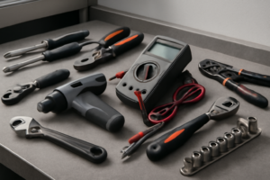
🔧 Required Tools
✔️ Difficulty & Cost
Difficulty: Moderate-Difficult (gas work)
Estimated Cost: $40-80
✔️ Repair Steps
Step 1: Turn off gas supply
Turn Off Gas Supply
1. Locate the gas shut-off valve on the flexible gas line connected to your range. This valve is positioned behind the range, approximately 6-12 inches above the floor, where the flexible gas connector meets the rigid gas pipe coming from your wall or floor.
2. Pull the range forward 12-18 inches away from the wall to access the valve. Grip the range by its sides near the front corners and slide it straight forward on the floor. The range weighs approximately 150-180 pounds, so use proper lifting technique with bent knees.
3. Position a flashlight to illuminate the gas connection area. You’re looking for a small lever or round knob valve on the gas line. The Frigidaire FCRG3052AS typically uses a 1/2-inch ball valve with a yellow or red handle.
4. Turn the valve handle perpendicular (90 degrees) to the gas pipe. When the gas is ON, the handle runs parallel to the pipe direction. When OFF, it forms a “T” shape or cross with the pipe. Rotate the handle clockwise until it stops and cannot turn further—this is the OFF position.
5. Verify the valve is completely closed by attempting to ignite one of the cooktop burners. Turn a burner knob to the LITE position and listen. You should hear no gas flow, and the burner should not ignite. Test all five burners (four standard burners plus center oval burner) to confirm zero gas flow.
6. Open a nearby window or exterior door to ventilate the area. Even with the valve closed, residual gas may remain in the line between the shut-off valve and the range burners.
7. Wait 5 minutes after closing the valve before proceeding with any disassembly work. This allows any residual gas in the lines to dissipate.
Troubleshooting Tips for This Step
**If the valve handle won’t turn:** The valve may be seized from age. Spray penetrating oil (like WD-40) around the valve stem, wait 10 minutes, then attempt to turn it again using slip-joint pliers with gentle, steady pressure. Never force it—if it doesn’t move after penetrating oil, call a licensed plumber to replace the valve before proceeding.
**If you smell gas after closing the valve:** The valve may not be seating properly. Turn all burner knobs to the OFF position. Evacuate the home immediately, do not use any electrical switches or create sparks, and call your gas company’s emergency line from outside.
**If the valve is missing or inaccessible:** Your installation does not meet code requirements. You must locate and turn off the main gas supply to your home, typically found at the gas meter outside. This valve operates the same way—turn perpendicular to the pipe to close.
**If you cannot locate any shut-off valve:** Check the floor directly behind the range’s left rear corner, or look for a valve on the wall 4-6 inches above floor level. Some installations have the valve recessed in the wall behind a small access panel.
Step 2: Disconnect power
Disconnect Power
1. Locate the gas shutoff valve on the gas supply line behind the range, typically on the floor or wall 2-4 inches from the left rear leg of the appliance. Turn the valve handle 90 degrees clockwise until it’s perpendicular to the gas line. The valve is now closed when the handle points across the pipe rather than along it.
2. Move to your home’s electrical panel and identify the circuit breaker labeled for the kitchen range. This is typically a single 15-amp or 20-amp breaker (not a double-pole breaker like an electric range would use, since this is a gas range requiring only 120V for igniters and controls).
3. Flip the breaker to the OFF position. The switch will move from pointing toward the center of the panel to pointing toward the outside edge.
4. Return to the range and turn one of the front burner knobs to the LITE position while pressing the igniter button. You should hear no clicking sound. If you still hear clicking, return to the electrical panel and verify you turned off the correct breaker.
5. Pull the range away from the wall approximately 12-18 inches to access the rear panel where the power cord connects. You may need a second person for this, as the range weighs approximately 150-200 pounds.
6. Look at the lower rear panel, approximately 8 inches from the bottom and centered horizontally. You’ll see the power cord entering through a strain relief connector. The cord has 3 wires: black (hot), white (neutral), and green or bare copper (ground).
7. Using a 5/16-inch nut driver or socket wrench, remove the single screw securing the rear lower access panel (approximately 4 inches wide by 6 inches tall). Set the screw aside in a container.
8. Remove the access panel by pulling it straight back. Inside, you’ll see the terminal block where the power cord connects, mounted on a white or silver bracket.
9. Identify the three wire connections on the terminal block: the black wire connects to a brass terminal on the left, the white wire connects to a silver terminal in the center, and the green/bare wire connects to a green grounding screw on the right.
10. Using a flathead screwdriver, loosen (but do not remove) each terminal screw by turning counterclockwise 4-5 full rotations until the wire loop can slide out freely.
11. Remove the black wire first, then white, then green. Let the power cord hang loosely behind the range.
Troubleshooting Tips
**If the igniter still clicks after turning off the breaker:** You’ve turned off the wrong circuit. Test each kitchen circuit breaker individually until the clicking stops.
**If terminal screws are corroded or stripped:** Use penetrating oil and wait 10 minutes before attempting removal. For stripped screws, use needle-nose pliers to grip the screw head while turning.
**If wires accidentally pull out of the power cord:** This requires power cord replacement. Note which colored wire came from which position in the cord’s molded plug before proceeding.
**Verification:** Once disconnected, use a non-contact voltage tester on the terminal block brass and silver terminals. The tester should not light up or beep, confirming zero voltage present.
Step 3: Remove control panel
Remove Control Panel
1. Locate the two Phillips-head screws at the top front corners of the control panel, positioned approximately 1 inch down from the top edge and 2 inches in from each side edge.
2. Using a Phillips #2 screwdriver, remove both screws by turning counterclockwise. Each screw is approximately 1 inch long with a silver finish. Set these screws aside in a container.
3. Locate the two additional Phillips-head screws at the rear top edge of the control panel, accessible from above when looking down at the range. These screws are positioned 3 inches in from each side edge.
4. Remove both rear screws using the same Phillips #2 screwdriver, turning counterclockwise. These screws are identical to the front screws.
5. Grasp the control panel at both sides, approximately 6 inches from each edge, and lift it upward about 2 inches. The panel will pivot forward at the bottom edge.
6. Tilt the panel forward approximately 45 degrees until it rests at an angle, exposing the wire harnesses behind it.
7. Identify the wire harnesses connected to the control panel. You will see two main connectors: a white 6-wire connector on the left side and a black 8-wire connector on the right side, both located approximately 4 inches from their respective edges.
8. At the white 6-wire connector, you’ll see: two red wires (hot/power), one black wire (hot/load), one white wire (neutral), one green wire (ground), and one yellow wire (signal). Press the release tab on top of the connector housing with your thumb while pulling the connector straight back toward you with your other hand.
9. At the black 8-wire connector, locate the gray release lever on the right side of the connector. Push the lever toward the left while pulling the connector straight back.
10. Move both disconnected wire harnesses toward the back of the range, positioning them flat against the rear wall to prevent interference during panel removal.
11. Lift the control panel completely away from the range and set it aside on a padded surface, display side up.
Troubleshooting Tips
**If individual wires pull out of connectors during disconnection:** Match wire colors to the corresponding colored terminals inside the connector housing. Red wires connect to red/brass terminals, black to black/dark terminals, white to silver/white terminals, green/yellow to green ground terminals. Insert the bare wire end into the terminal slot until you hear a click, typically requiring 1/4 inch insertion depth.
**If wire connectors won’t release:** The white connector requires 5-8 pounds of pulling force while the tab is depressed. The black connector’s gray lever must move a full 1/4 inch to the left. Do not pull on individual wires—always grip the connector housing.
**To verify correct wire reconnection during reassembly:** Pull each connector with 3-5 pounds of force—it should not separate. The release tabs should be fully returned to their locked positions, sitting flush with the connector housing rather than protruding upward.
**Common mistake:** Forcing the control panel forward without fully disconnecting both harnesses will damage wire terminals. Verify both connectors are completely separated before final panel removal.
Step 4: Disconnect gas line from valve
Disconnect Gas Line from Valve
1. Locate the gas supply line connecting to the back of the burner valve you’re replacing – it’s a 3/8-inch diameter brass or aluminum pipe entering the valve body from the rear manifold.
2. Use an adjustable wrench to grip the valve body itself (the hexagonal fitting on the valve where the gas line connects). Set the wrench opening to match the hex nut size, typically 5/8-inch or 11/16-inch.
3. With a second adjustable wrench, grip the compression nut or flare nut on the gas line itself, positioned directly behind where it meets the valve. This nut is typically 1/2-inch or 9/16-inch.
4. Hold the valve body steady with your first wrench (preventing the valve from turning). Using the second wrench on the gas line nut, turn counterclockwise to loosen. Apply firm, controlled pressure – the connection may be tight from factory installation.
5. Once the nut breaks free (you’ll feel it give slightly), continue turning counterclockwise by hand until the nut fully disengages from the valve threads – approximately 6-8 full rotations.
6. Pull the gas line straight back away from the valve body. You’ll see a brass flare fitting or compression ring at the end of the pipe – this is normal and should remain attached to the gas line.
7. Inspect the wire bundle running alongside the gas line near the valve – typically 2-4 wires (often white, blue, or black insulation) leading to the valve’s spark electrode and thermocouple. Push this wire bundle 2-3 inches to the side, away from the valve mounting area, to prevent interference when removing the valve. Secure the wires temporarily against the side wall of the range cavity using your hand or draping them over an adjacent component.
8. Check the end of the gas line you just disconnected – the brass flare seat or compression ferrule should be smooth and undamaged. If you see deep grooves, scratches, or deformation, the flare fitting must be replaced before reconnecting to the new valve.
Troubleshooting This Step
**If the gas line nut won’t loosen**: Spray penetrating oil (like PB Blaster) at the connection point where the nut meets the valve threads. Wait 5 minutes, then retry. Do not force – overtightening or forcing can crack the valve body or strip threads.
**If the gas line rotates with the nut instead of unscrewing**: The line itself may be turning in the manifold. Place a third wrench on the manifold connection point (where the gas line enters the main manifold pipe, typically 8-10 inches behind the valve) to hold it stationary while loosening the valve connection.
**If you accidentally disconnect wires from the valve during this step**: The igniter wire (typically white or blue) connects to a single electrode terminal on the valve side. The thermocouple wires (typically two wires with spade connectors) attach to terminals marked with a polarity symbol. Match the connector shapes – spade connectors only fit one way onto their respective terminals.
Step 5: Remove valve mounting
Remove Valve Mounting
1. Locate the two hex-head mounting bolts securing the valve assembly to the gas manifold pipe. These bolts are positioned on either side of the valve body, approximately 1.5 inches apart, and require a 5/16-inch socket wrench or nut driver.
2. Position your 5/16-inch socket wrench on the left mounting bolt. Turn counterclockwise 8-10 full rotations until the bolt is completely free. Set this bolt aside in your parts tray.
3. Support the valve body with your non-dominant hand from underneath to prevent it from dropping when the second bolt is removed. The valve assembly weighs approximately 8-10 ounces and can swing downward once freed.
4. Remove the right mounting bolt using the same 5/16-inch socket wrench, turning counterclockwise 8-10 full rotations. Keep your supporting hand under the valve throughout this process.
5. Pull the valve assembly straight back away from the gas manifold pipe. You’ll need to apply 3-5 pounds of steady pulling force to separate the valve inlet from the manifold connection. The valve should slide off with a slight resistance from the rubber O-ring seal.
6. Inspect the brass inlet fitting on the back of the valve. You should see a black rubber O-ring seated in a groove around the inlet pipe. This O-ring creates the gas seal and must remain on the valve (not stuck in the manifold pipe).
7. Check the manifold pipe opening where the valve was connected. If the black O-ring is stuck inside the manifold pipe instead of on the valve, use needle-nose pliers to grip and extract it. Pinch the O-ring edge and pull straight out with firm, steady pressure.
8. Set the old valve assembly on your work surface with the gas inlet facing up to prevent dirt or debris from entering the gas pathway.
Troubleshooting Tips for This Step
**If mounting bolts won’t turn**: The bolts may have thread-lock compound or corrosion. Apply penetrating oil (like PB Blaster) to the bolt threads, wait 10 minutes, then retry. Rock the wrench back and forth 1/4 turn in each direction to break the seal before attempting full removal.
**If the valve won’t pull free from the manifold**: The O-ring may be creating excessive friction. Grip the valve body firmly and twist it clockwise then counterclockwise 1/4 turn while pulling backward. This rotational movement breaks the O-ring seal without damaging it.
**If you drop the mounting bolts**: These bolts are critical for proper gas seal compression. Retrieve them immediately and inspect the threads. If threads are damaged or stripped, you must obtain replacement 5/16-inch hex bolts, 1 inch length, with standard threading before reassembly.
**If the O-ring tears during removal**: You must replace it with a new O-ring (standard size: 1/2-inch ID, 3/4-inch OD, Buna-N material). A damaged O-ring will cause gas leaks and cannot be reused under any circumstances.
Step 6: Install new valve
Install New Valve
1. Position the new burner valve at the mounting location on the manifold bracket, aligning the valve’s threaded inlet pipe (the brass tube extending from the valve body) with the corresponding hole in the manifold where the old valve was removed.
2. Hand-thread the valve onto the manifold by rotating clockwise 3-4 complete turns until finger-tight. The valve body should be positioned with the control shaft pointing toward the front of the range.
3. Using a 7/16-inch open-end wrench, grip the hexagonal brass fitting at the base of the valve where it connects to the manifold. Turn clockwise an additional 1.5 turns until firmly seated—you’ll feel resistance increase significantly when properly tightened. Do not overtighten, as this can crack the brass fitting.
4. Locate the gas supply tube (a flexible braided stainless steel or aluminum tube) that you previously disconnected. Align the flared end of this tube with the outlet port on the new valve (opposite side from the manifold connection).
5. Thread the compression nut on the gas supply tube clockwise onto the valve outlet by hand until fully seated, approximately 4-5 turns.
6. Using a 3/8-inch wrench on the valve body for support and a 1/2-inch wrench on the compression nut, tighten the nut an additional 1 full turn. You’ll see the brass flare compress slightly against the valve seat.
7. Position the mounting bracket (the metal strip with screw holes) over the valve body, aligning the two holes in the bracket with the threaded holes on the manifold bracket beneath.
8. Insert the two #8-32 hex head screws through the bracket holes and thread them by hand into the manifold bracket holes. Using a 5/16-inch nut driver or socket, tighten each screw in an alternating pattern (first one, then the other) until the bracket holds the valve firmly without movement—approximately 8-10 inch-pounds of torque.
9. Verify the valve control shaft extends through the front control panel opening and rotates freely through a full 90-degree arc from the OFF position (perpendicular to the range front) to the HIGH position (parallel to the range front).
Troubleshooting This Step
**If the valve won’t thread onto the manifold:** The threads may be cross-threaded. Back the valve out completely, inspect both the valve threads and manifold threads for damage or debris, clean with a wire brush, and restart the threading process, ensuring the valve enters perfectly straight.
**If the gas supply tube won’t align with the valve outlet:** The valve may be rotated incorrectly. Loosen the valve 1/4 turn, rotate the valve body slightly left or right until the outlet aligns with the tube, then retighten.
**If the mounting bracket doesn’t align with screw holes:** The valve is positioned too high or low on the manifold. Slightly loosen the main valve connection, adjust the valve up or down 1-2mm, retighten, and check bracket alignment again.
**If the control shaft doesn’t rotate smoothly:** Remove the mounting bracket screws and verify nothing is binding the shaft. The shaft should spin freely before the bracket is installed—if not, the valve is defective and must be replaced.
Step 7: Check for leaks
Check for Leaks
1. Turn on the gas supply valve by rotating it counterclockwise until the handle aligns with the gas line (parallel position). You’ll hear a faint hissing sound for 1-2 seconds as gas fills the lines.
2. Locate your leak detection solution. Mix 1 tablespoon of liquid dish soap with 1 cup of water in a spray bottle, or purchase commercial leak detector solution like Leak-Tec or similar product.
3. Spray or brush the soapy solution generously onto the newly installed burner valve connection where the gas supply tube attaches. Apply solution to a 2-inch radius around the entire connection point, ensuring complete coverage of all threaded areas and the valve body seam.
4. Watch the connection for 30-60 seconds. A gas leak appears as growing bubbles that expand and multiply, similar to blowing soap bubbles. No leak shows as wet surface with no bubble formation.
5. Spray the connection at the gas manifold (the brass fitting where the valve connects to the main gas line, located at the rear of the range beneath the cooktop). Apply solution completely around the threaded connection and watch for 30-60 seconds.
6. Check the valve control stem where it enters the valve body (the point where you’ll turn the knob). Spray solution around the stem shaft and observe for bubbles indicating a defective valve seal.
7. Turn the burner control knob to HIGH position. Listen for gas flowing (soft hissing sound) and spray additional solution on all previously checked connections while gas flows. Leaks often appear under pressure when the valve opens.
8. Turn the control knob to OFF position after 10 seconds of checking under flow conditions.
9. Check each adjacent burner valve connection by repeating steps 3-8. Even though you didn’t replace these valves, the vibration from your work may have loosened existing connections.
**If you detect a leak (bubbles forming):**
10. Turn off the gas supply valve immediately by rotating clockwise until perpendicular to the gas line.
11. Wait 5 minutes for gas to dissipate from the lines.
12. Use a 9/16-inch wrench on the valve inlet fitting and tighten clockwise by 1/4 turn (90 degrees). Do not over-tighten as brass fittings can crack.
13. Repeat steps 1-6 to recheck. If bubbles still appear, turn off gas, disconnect the fitting, inspect the flare connection for debris or damage, and reinstall with new pipe thread sealant rated for gas (yellow Teflon tape or pipe dope marked “for gas”).
**If no leaks are detected:**
14. Wipe away all soapy solution with a damp cloth to prevent residue buildup.
15. Turn all burner knobs to HIGH position one at a time, verifying each burner ignites within 4 seconds and produces a blue flame with yellow tips no longer than 1/2 inch.
16. Verify the repaired burner maintains steady flame at both HIGH and SIMMER settings without flame lifting (flame separating from burner ports) or flashback (flame burning inside the burner tube).
📝 Next Steps: This post will be expanded by Claude AI with:
- Detailed step-by-step instructions with explanations
- Safety warnings and precautions
- Tool recommendations and usage tips
- Troubleshooting common issues
- Product recommendations (repair kits, tools) from Amazon via Firecrawl
- Affiliate links integrated naturally into sentence form
🔧 Recommended Parts & Tools
You can find the replacement part you need, such as this SUNRISE Heavy Duty Natural Gas Range Stove Top Burner Valve (2 packs). Made i…, on Amazon. For this repair, you’ll need a MHP Charmglow Gas Lamp Repair Kit Mantels, Burner, NG Valve DMI-N which includes all the necessary components. You can find the replacement part you need, such as this 316405000 Range Oven Door Gasket (80″ Long/ 16 Mounting Clips)- Compatible wi…, on Amazon. You can find the replacement part you need, such as this Frigidaire 5304506548 Range Surface Burner Valve, on Amazon.
As an Amazon Associate, I earn from qualifying purchases.
How Much Does This Repair Cost?
Replacement burner valve 316538502 typically runs $40–$65 through online parts suppliers. A professional technician will usually charge $150–$250 total once you factor in the service call, labor, and part markup — making this a worthwhile DIY repair if you’re comfortable working with gas connections.
Recommended Products
These are the parts and tools we recommend for this repair, based on compatibility and customer reviews:
- Conversion Kit Compatible with Frigidaire Range LP Conversion Kit,Natural Gas to Propane LPG Conversion Kit for Frigidaire Series Range, Replaces 4980407 316243720 316243721 AP7213138 A22390101.
- StoveGuard Model# FCRG3052AS, USA-Made, Custom Designed Precision Cut Stove Cover for Gas Stove Top, Compatible With Lite Frigidaire Gas Range Stove
As an Amazon Associate, I earn from qualifying purchases.