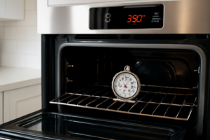
🔩 Oven Igniter Repair Guide for Frigidaire FCRG3052AS (Gas Range)
💡 This repair guide will be expanded with detailed instructions. Claude AI will add comprehensive explanations, safety tips, troubleshooting advice, and product recommendations.
🔨 Pro Tip from Dave
On the FCRG3052AS, a lot of techs overlook that the igniter can test as functional with a multimeter but still be too weak to open the gas valve — the igniter must draw at least 3.2 amps to trigger the valve. Don’t skip the amp draw test before assuming the igniter is good. Also, part 316489400 is a direct OEM fit; avoid universal igniters on this model as they frequently cause intermittent lighting issues.
🔍 Symptoms
Won’t light, takes long time to ignite
🔧 Part Numbers
- 316489400
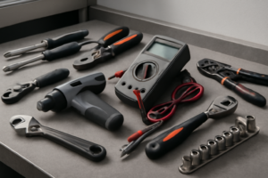
🔧 Required Tools
- 1/4″ nut driver
- Phillips screwdriver
✔️ Difficulty & Cost
Difficulty: Moderate
Estimated Cost: $30-60
✔️ Repair Steps
Step 1: Turn off gas and power
Turn Off Gas and Power
Main Steps
1. Locate the gas shutoff valve behind the range. Pull the range forward 12-18 inches from the wall to access the rear. You’ll see a metal gas line with a lever or knob valve approximately 6 inches above the floor.
2. Turn the gas valve handle perpendicular (90 degrees) to the gas pipe. When OFF, the handle points across the pipe, not along it. The valve should stop firmly in this position and require moderate force to turn.
3. Open a kitchen window or exterior door to ventilate the area for 5 minutes before proceeding.
4. Locate your home’s electrical panel (breaker box). Find the breaker labeled for the kitchen range, typically a 40-50 amp double-pole breaker (two switches connected together) or a single 15-20 amp breaker depending on your installation.
5. Switch the range breaker to the OFF position. The toggle should move completely to the opposite side with an audible click.
6. Return to the range and attempt to turn on a surface burner control knob. The igniter should make NO clicking sound. If you hear clicking, the power is still on—return to the breaker panel and verify you switched the correct breaker.
7. Unplug the range power cord from the wall outlet behind the unit. The outlet is typically located 6-12 inches above the floor, centered behind the range. Grasp the plug body firmly (not the cord) and pull straight out with steady pressure.
8. Verify power is disconnected by pressing any buttons on the range’s electronic control panel. The display should remain completely dark with no response.
9. Push the range back closer to the wall, leaving 6-8 inches clearance for working access to the rear and bottom.
Troubleshooting Tips for This Step
**Gas valve won’t turn or is stuck**: Apply penetrating oil (WD-40) to the valve stem, wait 10 minutes, then use adjustable pliers wrapped with a cloth to turn the handle. Never force it hard enough to break the valve.
**Unsure if gas is off**: Check your cooktop burners—turn a knob to ignite position. You should hear clicking from the igniter but see NO flame. If flame appears, the gas is still flowing.
**Cannot identify correct breaker**: Turn on the oven, then flip breakers one at a time until the oven display goes dark. Mark this breaker clearly with tape labeled “RANGE.”
**Range is hardwired (no plug)**: The power cable will enter a metal junction box on the back of the range. Do NOT attempt to disconnect hardwired installations without first turning off the breaker. Verify power is off using a non-contact voltage tester at the junction box.
**Breaker immediately trips when turned back on later**: This indicates a short circuit. Do not reset the breaker repeatedly. Verify all wire connections made during reassembly are correct and not touching metal housing.
**Gas smell present**: If you smell gas (rotten egg odor) at any point, immediately leave the area, call your gas utility company emergency line from outside, and do not continue repairs.
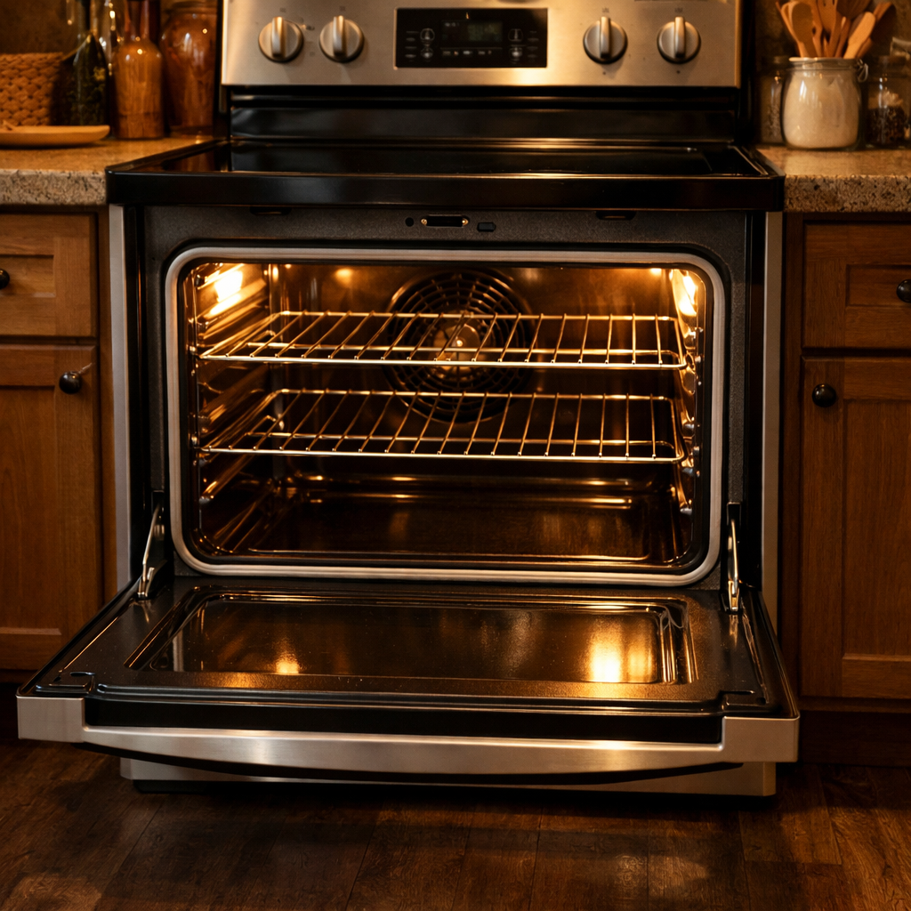
Step 2: Remove oven bottom
Remove Oven Bottom
1. Open the oven door fully until it stops at its widest position (approximately 90 degrees from closed).
2. Look inside the empty oven cavity at the bottom surface. You’ll see a flat metal panel (the oven bottom) that covers the burner assembly beneath it.
3. Locate the two front corners of the oven bottom panel. Each corner has a curved lip that sits in a slot in the oven floor, approximately 1 inch from the front edge and 2 inches from each side wall.
4. Grasp the oven bottom panel at both front corners with both hands, placing your fingers under the front edge of the panel.
5. Lift the front edge of the panel straight up approximately 1 inch until the front lip clears the retaining slots. You’ll feel it release from the slots.
6. Pull the entire panel forward toward you approximately 3-4 inches while keeping it lifted. The rear edge of the panel rests on a support lip and will slide forward as you pull.
7. Once the panel has moved forward 3-4 inches, tilt the front edge upward at a 30-degree angle while continuing to pull forward. This prevents the panel from catching on the side walls.
8. Remove the panel completely from the oven cavity and set it aside on a protected surface. The panel measures approximately 24 inches wide by 18 inches deep and weighs about 3-4 pounds.
9. Look at the now-exposed burner area. You’ll see the flat metal burner tube running from back to front, with the white ceramic igniter visible at the rear of the burner tube (looks like a small rectangular block, approximately 1.5 inches long).
10. Inspect for any wire harnesses running along the left or right side of the exposed area. On this model, you’ll typically see a wire bundle on the left side connecting to the igniter. These wires should not obstruct your access at this point—they connect at the rear where you’ll work in the next step.
Troubleshooting This Step
**If the oven bottom panel won’t lift at the front corners:** The panel may be stuck due to food debris in the slots. Insert a flathead screwdriver into the slot beside the panel edge and gently pry upward while lifting with your other hand. Clean the slots with a damp cloth before reinstalling.
**If the panel catches when pulling forward:** Lower the front edge slightly (to horizontal) and ensure you’ve pulled it far enough forward (full 3-4 inches) before tilting it upward for removal. The rear edge must clear the support lip before tilting.
**If you see screws holding the oven bottom:** This model uses a lift-and-pull design without screws. If screws are present, you may have a different model variant. Remove visible screws (typically 2-4 Phillips-head screws at the front edge) using a #2 Phillips screwdriver before attempting to lift the panel.
Step 3: Disconnect igniter wires
Disconnect Igniter Wires
1. Locate the wire harness connector attached to the oven igniter. You’ll find a white plastic connector approximately 4 inches from the igniter, positioned near the left side of the oven burner box where the igniter wires exit through a rubber grommet.
2. Identify the two wires in this connection: both wires are typically purple or violet (Frigidaire uses purple for igniter circuits). These wires are not polarized, meaning either wire can connect to either terminal during reassembly.
3. Examine the white plastic connector housing. You’ll see a small rectangular tab on one side of the connector, approximately ¼ inch wide and protruding 1/8 inch from the connector body.
4. Press down firmly on the locking tab with your thumb while simultaneously pulling the two halves of the connector apart. Apply 3-5 pounds of pressure—the connector requires firm pressure to release but should not need excessive force.
5. If the connector does not separate after pressing the tab, check for a second locking mechanism. Some FCRG3052AS models have a wire clip that wraps around the connector. Slide this clip toward the igniter end (away from the oven wall) approximately ½ inch to release it before separating the connector.
6. Once separated, move the wall-side connector (the one leading to the oven’s control system) back toward the rear of the oven cavity to keep it out of your work area. Secure it by tucking it behind the metal bracket on the left side of the burner box, approximately 6 inches from the front edge.
7. Examine both connector halves. The male pins should be straight and clean. The female sockets should show no signs of melting, blackening, or corrosion. Discolored or melted connectors indicate overheating and both the connector and wiring harness will need replacement along with the igniter.
Troubleshooting: If Wires Become Disconnected
**If a wire pulls out of the connector housing:** The purple wires are not polarized for this igniter connection. Push the bare wire end (with its attached metal terminal) back into the corresponding slot in the white connector housing until you hear and feel a distinct click. The terminal should lock into place and resist pulling out with 2-3 pounds of force.
**If you’re unsure which wire goes where:** Since both wires are purple and the connection is non-polarized, either wire can connect to either position. However, keep each wire with its original connector half—the wall-side wires stay with the wall-side connector, the igniter-side wires stay with the igniter connector.
**Common mistake:** Pulling the wires instead of the connector housing. This can dislodge the metal terminals from inside the plastic connector. Always grip the plastic connector body when separating or connecting.
**Verification:** After any wire reconnection during reassembly, tug each wire gently with 2-3 pounds of force. A properly seated terminal will not pull free from the connector housing.
Step 4: Remove mounting bracket
Remove Mounting Bracket
1. Locate the two mounting screws securing the igniter bracket to the oven burner tube. These screws are positioned on either side of the igniter, approximately 1.5 inches apart, and are typically 1/4-inch hex head screws.
2. Using a 1/4-inch nut driver or socket wrench, turn the right mounting screw counterclockwise 3-4 full rotations to remove it completely. Place this screw in your parts container.
3. Support the igniter and bracket assembly with your non-dominant hand by cupping it from underneath while removing the second screw to prevent it from dropping.
4. Remove the left mounting screw using the same 1/4-inch nut driver, turning counterclockwise until the screw releases completely.
5. With both screws removed, gently pull the mounting bracket straight away from the burner tube. The bracket should slide off easily with approximately 1/4 inch of clearance. If resistance occurs, verify both screws are fully removed and check for corrosion around the mounting holes.
6. Examine the wire bundle still connected to the igniter. You’ll see two wires: one white wire and one white wire with a purple or blue stripe. These wires will likely drape downward toward the oven floor once the bracket is free.
7. Carefully guide the wire bundle through any clips or routing channels along the burner tube as you move the bracket assembly. The wires typically run along the left side of the burner tube and may pass through a metal clip approximately 4 inches from where the bracket was mounted.
8. Set the entire bracket and igniter assembly (still with wires attached) on a clean towel on the oven floor, positioning it away from the burner opening to prevent damage during the next step.
Troubleshooting Tips for This Step
**If screws won’t turn:** Apply penetrating oil (like WD-40) around the screw base and wait 5 minutes. The heat from previous oven use may have caused corrosion. Use steady pressure without forcing to avoid stripping the screw head.
**If the bracket won’t pull free after screw removal:** Check for a third mounting point. Some FCRG3052AS units manufactured before 2018 have a small metal tab at the top of the bracket that hooks over the burner tube. Lift the bracket upward approximately 1/8 inch, then pull away.
**If wires snag on metal edges:** The wire insulation can catch on sharp burner tube edges. Rotate the bracket slightly (15-20 degrees) while pulling to change the wire angle and release it from any catch points.
**If the mounting bracket is rusted to the burner tube:** Spray penetrating oil at the contact points where metal meets metal. Wait 10 minutes, then twist the bracket left and right (approximately 1/4 inch of movement each direction) while pulling to break the corrosion bond.
**Success verification:** The bracket should move freely in your hand with no metal-to-metal contact remaining with the oven. The igniter ceramic element should still be intact with no cracks visible.
Step 5: Install new igniter
Install New Igniter
1. Remove the new igniter from its packaging and inspect the ceramic body for any cracks or chips – a damaged igniter will fail immediately and cannot be used.
2. Locate the two wire leads extending from the new igniter’s ceramic housing – these wires are typically white or gray insulated and approximately 6-8 inches long.
3. Position the new igniter into the mounting bracket at the back left corner of the oven burner assembly, aligning the two mounting holes in the igniter’s metal bracket with the screw holes in the burner tube.
4. Insert the two hex head screws (5/16-inch hex head) through the mounting bracket holes and hand-tighten them into the burner tube threads.
5. Using a 5/16-inch nut driver or socket wrench, tighten each screw to finger-tight plus one-quarter turn – do not overtighten as the ceramic igniter body will crack under excessive pressure (stop when you feel resistance increase).
6. Verify the igniter tip is positioned 3/8 to 1/2 inch from the burner ports – the ceramic tip should sit directly adjacent to the gas outlet holes without touching metal.
7. Route the igniter’s two wire leads along the left side of the oven cavity toward the wire connector you previously disconnected, keeping wires away from any sharp metal edges.
8. Locate the white 2-pin wire connector with two wires (typically both white or one white/one gray) that you disconnected in the previous step – this connector should be hanging near the left side of the oven cavity.
9. Align the male plug from the new igniter with the female connector from the oven harness – the connector is keyed and will only fit one way, with a small tab on one side that matches a notch in the socket.
10. Push the two connectors together firmly until you hear and feel a distinct click – the connection is secure when the locking tab engages and you cannot pull the connectors apart without pressing the release tab.
11. Tug gently on each connector (pull with 2-3 pounds of force) to verify the connection is locked – the connectors should remain joined and not separate.
12. Position the connected wires along the left oven wall, ensuring they do not rest against the oven burner tube or hang down where they could contact the oven floor during operation.
Troubleshooting: Wire Connection Issues
**If the connector won’t join completely:** Inspect both the male pins and female sockets for bent pins or debris. Straighten any bent pins using needle-nose pliers, ensuring they align parallel to each other.
**If wires became disconnected from the plug terminals:** The igniter wires are not polarized – either wire can connect to either terminal. Strip 1/4 inch of insulation if needed and crimp the wire into the spade terminal, then slide the terminal into the connector housing until it clicks.
**If the igniter tip touches metal:** Loosen the mounting screws one-half turn and reposition the igniter body slightly away from the burner tube, then retighten.
**Connection verification:** A properly connected igniter will have no visible gap between the two connector halves and the locking tab will be fully engaged over the mating connector’s ledge.
📝 Next Steps: This post will be expanded by Claude AI with:
- Detailed step-by-step instructions with explanations
- Safety warnings and precautions
- Tool recommendations and usage tips
- Troubleshooting common issues
- Product recommendations (repair kits, tools) from Amazon via Firecrawl
- Affiliate links integrated naturally into sentence form
🔧 Recommended Parts & Tools
You can find the replacement part you need, such as this Frigidaire 5303935066 Burner Igniter for Oven Burners, Gold, on Amazon. For this repair, you’ll need a Repairwares Gas Range/Oven Igniter 316489400 316428500 IG94 AP3963540 3164285… which includes all the necessary components. You can find the replacement part you need, such as this 316489400 5304534663 Gas Range Oven Igniter Replacement Part, Replaces the fo…, on Amazon. You can find the replacement part you need, such as this Ismosm 4Pcs Nut Driver Set RC Tool Set Hex Nut Driver for RC Vehicle RC Helic…, on Amazon.
As an Amazon Associate, I earn from qualifying purchases.
How Much Does This Repair Cost?
The OEM igniter (part 316489400) typically runs $30–$55 online for DIY repair, making this one of the more affordable oven fixes. A professional repair on this model usually costs $150–$250 including parts and labor. Given the moderate difficulty, most handy homeowners can save significantly by doing it themselves.
Recommended Products
These are the parts and tools we recommend for this repair, based on compatibility and customer reviews:
- Repairwares Gas Range/Oven Igniter 316489402 5304509706 WB2X10016 316489408 AP6230715 PS12071409 Norton-501a 316119301 WB02X10016 (Flat Style Ignitor)
- Frigidaire 5303935066 Burner Igniter for Oven Burners, Gold
- 5304509706 316489402 Oven Igniter for Kenmore 790 Series, Frigidaire Gas Oven Igniter | Replaces PS12071409 WB02X10016 Norton-501a 316489408 Gas Range Oven Igniter
As an Amazon Associate, I earn from qualifying purchases.