🔩 Temperature Sensor Repair Guide for Wolf SO30TE/S/TH (Electric Wall Oven – High-End)
💡 This repair guide will be expanded with detailed instructions. Claude AI will add comprehensive explanations, safety tips, troubleshooting advice, and product recommendations.
🔨 Pro Tip from Dave
One gotcha I see constantly on the SO30TE/S/TH is technicians forcing the sensor probe out without first loosening the single mounting screw inside the oven cavity — it’s tucked near the back wall and easy to miss. Yanking it can damage the wiring harness connector, turning a $75 fix into a much costlier one. Always verify resistance on the new 806846 sensor before installing — it should read approximately 1080–1090 ohms at room temperature.
🔍 Symptoms
Inaccurate temperature, error codes
🔧 Part Numbers
- 806846
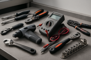
🔧 Required Tools
✔️ Difficulty & Cost
Difficulty: Easy
Estimated Cost: $50-100
✔️ Repair Steps
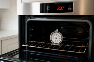
Step 1: Test sensor resistance
Test Temperature Sensor Resistance
Actions
1. Turn off the circuit breaker dedicated to your Wolf oven at your home’s electrical panel—this will be a 240V double-pole breaker labeled for the oven, typically 30-50 amps.
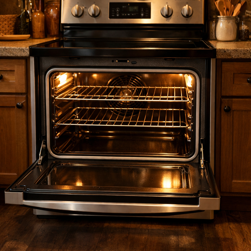
2. Open the oven door fully and remove all racks by sliding them toward you and lifting up when they reach the stop point.
3. Locate the temperature sensor probe at the upper rear wall of the oven cavity, approximately 4 inches from the top and centered left-to-right. It appears as a metal tube, 1/4 inch diameter, protruding 2-3 inches into the oven cavity.
4. Remove the two Phillips-head screws (#2 bit) securing the sensor mounting bracket to the rear wall. These screws are located directly behind the sensor probe.
5. Gently pull the sensor probe forward 6-8 inches until you see the wire connector behind the rear wall. You’ll feel slight resistance from the wiring.
6. Identify the wire connector: a white plastic 2-pin connector with two wires—one red wire and one white wire. The red wire connects to the sensor’s positive terminal; the white wire connects to the negative terminal.
7. Disconnect the 2-pin connector by squeezing the locking tab on top with your thumb while pulling the connector halves apart with steady pressure. The connector should separate with 5-10 pounds of force.
8. Set your multimeter to the resistance (Ω) setting, specifically the 200-ohm or 2K-ohm range.
9. Touch the multimeter’s red probe to one metal terminal on the sensor side of the connector (the side still attached to the sensor probe).
10. Touch the multimeter’s black probe to the other metal terminal on the same connector side.
11. Read the resistance value on the multimeter display. At room temperature (68-72°F), a functioning Wolf oven temperature sensor reads between 1,080 and 1,120 ohms. Write this number down.
12. If the reading shows “OL” (open loop) or infinity, the sensor is broken internally and must be replaced.
13. If the reading shows 0 ohms or near-zero, the sensor is short-circuited and must be replaced.
14. If the reading falls between 1,080-1,120 ohms, gently flex the sensor wire where it exits the probe tube while watching the multimeter display. The reading should remain stable. If it fluctuates more than 50 ohms, the internal wiring is damaged.
Troubleshooting This Step
**If the connector won’t disconnect:** The locking tab may be stuck with residue. Use a flathead screwdriver to gently pry the tab upward while pulling the connector apart.
**If wires pull out of the connector during disconnection:** Examine the connector pins. Red wire terminals are marked with a “+” or red dot on the connector housing. White wire terminals are unmarked or have a “-” symbol. Push the loose wire terminal back into its slot until it clicks—you’ll hear an audible snap when properly seated.
**If you’re unsure which terminal to test:** It doesn’t matter—temperature sensors have no polarity. Testing either direction (red-to-white or white-to-red) produces the same resistance reading.
**If your multimeter reads erratically:** Ensure your probe tips make firm contact with the bare metal terminals inside the connector, not the plastic housing. Press firmly and hold steady for 3-5 seconds.
Step 2: Disconnect power
Disconnect Power
1. Locate your home’s main electrical panel (breaker box), typically found in the basement, garage, utility room, or exterior wall.
2. Open the breaker panel door by pulling the handle or lifting the latch on the front cover.
3. Identify the breaker labeled “Wall Oven,” “Wolf Oven,” or “Kitchen Oven.” High-end Wolf ovens typically use a dedicated 240-volt double-pole breaker (two switches connected by a bridge) rated at 30-50 amps. The breaker will be wider than standard 120-volt breakers.
4. Switch the breaker to the OFF position by pushing the toggle completely to the right or downward (depending on panel orientation). You should feel a definite click. The toggle should align with other “OFF” breakers and may show a white or orange indicator.
5. Place a piece of masking tape across the breaker and write “DO NOT TURN ON – REPAIR IN PROGRESS” to prevent accidental reactivation.
6. Return to the oven and press any control panel button. The display should be completely dark with no lights, sounds, or indicator LEDs. If anything illuminates or makes sound, the wrong breaker was switched off—return to the panel and locate the correct breaker.
7. Locate the junction box behind the oven. For Wolf SO30TE models, pull the oven partially away from the wall (4-6 inches) to access the rear panel. The junction box is a metal box measuring approximately 4×4 inches, positioned on the upper-right rear of the oven chassis, 3-4 inches below the top edge.
8. Use a non-contact voltage tester (also called a voltage pen or voltage detector). Hold the tester’s tip within 1/2 inch of the junction box cover. Press the tester’s button—it should NOT beep, light up, or vibrate. If it does, return to the breaker panel and verify the correct breaker is off.
9. Remove the junction box cover plate by unscrewing the single center screw using a flathead screwdriver. The screw turns counterclockwise.
10. Test again inside the junction box with the voltage tester. Touch the tester tip to each visible wire connection and wire nut. You’ll see 4 wires: two black (hot), one white (neutral), and one bare copper or green (ground). The tester should show NO voltage on any wire.
Troubleshooting: Voltage Still Present
– **If voltage tester activates**: The oven is still powered. Check for a second breaker labeled differently (e.g., “Range,” “Kitchen Appliances”). Some installations have multiple circuits. – **If you cannot locate the breaker**: Switch off the main breaker (largest breaker at the top of the panel, usually 100-200 amps). This cuts power to your entire home but ensures safety. – **If voltage tester batteries are dead**: Replace batteries (typically AAA or 9V) or use a multimeter set to AC voltage mode. Touch black probe to ground wire and red probe to each black wire—reading should be 0 volts.
Step 3: Remove sensor bracket
Remove Sensor Bracket
1. Locate the sensor bracket—a thin metal L-shaped bracket approximately 2 inches long—positioned at the upper left rear corner of the oven cavity, about 3 inches down from the top panel and 4 inches from the left wall.
2. Identify the single Phillips-head screw (size #2) securing the bracket to the rear cavity wall. The screw head will be visible through a slot in the bracket.
3. Check for the wire bundle running along the left side of the cavity behind the bracket. You’ll see 2 wires (typically white and red) leading from the sensor probe. These wires may rest against the bracket or pass underneath it.
4. Push the wire bundle approximately 1 inch to the left, away from the bracket, to create working clearance. The wires have enough slack to move without resistance—if you feel tension, trace the wires back to the sensor connection point to verify they aren’t snagged on any metal edges.
5. Insert your Phillips-head #2 screwdriver into the screw head at a 90-degree angle to the wall surface. The screw penetrates approximately 3/4 inch into the cavity wall.
6. Turn the screw counterclockwise 8-10 full rotations until it releases completely from the wall. The screw will remain partially threaded in the bracket mounting hole—this is normal.
7. Remove the screw from the bracket hole and set it aside in your parts container. This screw will be reused during reassembly.
8. Grasp the bracket with your thumb and forefinger at the horizontal section (the part that held the screw). Pull straight outward from the wall with steady pressure—approximately 2-3 pounds of force.
9. The bracket will slide forward off the sensor probe. The probe itself (a thin metal tube about 4 inches long) will remain inserted through the rear wall—do not pull the probe out at this stage.
10. Inspect the bracket for a small rubber grommet or insulation washer that sits between the bracket and sensor probe. If present, this grommet (typically gray or black, 1/4 inch diameter) may stick to either the bracket or the probe.
11. If the grommet stayed on the probe, slide it off the probe end and keep it with the bracket for reassembly.
Troubleshooting Tips for This Step
**If the bracket won’t pull free**: Check that the sensor wires haven’t looped behind the bracket during previous service. Slide a finger behind the bracket to feel for trapped wires, then redirect them to the side.
**If the screw spins without backing out**: The wall insert may have stripped. Continue turning—the screw should eventually pull forward with the damaged insert. You’ll need a new insert (Wolf part #806880) or use a slightly larger diameter screw (#8 instead of #6) during reassembly.
**If the grommet tears or is missing**: The sensor will still function, but temperature readings may be less accurate. Order Wolf part #806732 (sensor grommet) before reassembly.
**If wires pull from the sensor connection during bracket removal**: Stop immediately and verify the wires aren’t under tension from being pinched elsewhere in the cavity. The sensor connector should have at least 6 inches of slack.
Step 4: Disconnect wires
Disconnect Wires from Temperature Sensor
1. Locate the wire connector attached to the temperature sensor probe. This is a small rectangular white plastic connector, approximately 1 inch long, located where the sensor wire meets the sensor probe tip at the back left corner of the oven cavity.
2. Identify the two wires inside the connector. You will see: – One **white wire** (neutral/sensor signal) – One **red wire** (positive/sensor signal) Note: These wires carry low voltage (5-12V) from the control board and are safe to handle with power off.
3. Grip the white plastic connector body firmly between your thumb and forefinger. Do NOT pull on the wires themselves, as this can damage the wire crimp connections inside the connector.
4. Press the small release tab on the top of the connector with your thumbnail or a flathead screwdriver (1/8 inch wide). The tab is a small rectangular protrusion, approximately 1/8 inch wide, centered on the connector body.
5. While pressing the release tab, pull the connector straight away from the sensor probe terminals. Apply steady pressure—the connector requires approximately 3-5 pounds of force to release. You will feel it pop free when the locking tab clears.
6. Once disconnected, examine the wire terminals inside the connector. The white wire connects to the left terminal, and the red wire connects to the right terminal when viewing the connector with the release tab facing up.
7. Move the disconnected wire connector 6-8 inches away from the sensor mounting location by routing it toward the left side panel. This prevents accidental reconnection or interference during sensor removal.
8. If the wire bundle has tension pulling it back toward the control board, use a plastic zip tie to temporarily secure it to the nearby wire harness that runs vertically along the left oven wall, approximately 4 inches from the back panel.
Troubleshooting: What If Wires Become Disconnected from the Connector?
If individual wires pull out of the white connector housing:
1. Look at the sensor probe terminals you just disconnected. The terminal on the LEFT (when facing the oven from the front) connects to the WHITE wire. The terminal on the RIGHT connects to the RED wire.
2. Inspect the wire end. You should see a small metal crimp terminal (female spade terminal, 0.187 inches wide).
3. If the crimp terminal is missing or damaged, you must replace the entire sensor assembly—individual wire repair requires specialized crimping tools.
4. To reinsert a wire into the connector: Slide the metal terminal back into the matching slot (white wire to left slot, red wire to right slot) until you hear a click. Tug gently with 2-3 pounds of force—the wire should not pull free.
Verification Steps
1. Gently tug each wire at the connector body (not the wire itself). Neither wire should move or pull out.
2. Visually confirm the release tab moves freely and is not broken.
3. The sensor probe terminals should be clean and free of corrosion. If you see green or white residue, clean with rubbing alcohol and a cotton swab before installing the new sensor.
Step 5: Install new sensor at same depth
Install New Sensor at Same Depth
1. Remove the new Wolf temperature sensor from its packaging and verify the probe diameter matches the old sensor (typically 1/4 inch diameter) by placing them side-by-side.
2. Locate the 2-wire connector on the new sensor – you’ll see two wires: one red (signal) and one white (ground). These wires are typically 18-24 inches long.
3. Insert the metal probe tip of the new sensor into the mounting hole in the rear oven wall. The hole is a snug fit – push firmly with steady pressure until the probe enters completely.
4. Slide the sensor probe inward until the mounting bracket (the metal clip 3-4 inches from the probe tip) contacts the outer oven wall surface. This ensures the probe extends to the correct depth into the oven cavity.
5. While holding the sensor in place with one hand, use your Phillips-head #2 screwdriver to insert the mounting screw through the bracket hole. Thread it clockwise into the existing hole in the oven wall.
6. Tighten the mounting screw until the bracket is firmly secured and the sensor cannot rotate or pull outward. The bracket should sit flat against the oven wall with no gaps.
7. Route the sensor wires downward along the right side of the oven cavity wall, keeping them away from any heating elements. The wires should hang naturally without tension.
8. Connect the 2-wire spade connector from the new sensor to the matching connector from the oven’s wiring harness. Match the wire colors: red sensor wire connects to the red harness wire, white sensor wire connects to the white harness wire.
9. Push the connectors together firmly until you hear or feel a click. The metal spade terminals should be completely hidden inside the plastic connector housing – no exposed metal should be visible.
10. Verify the connection by gently tugging on both sides of the connector – it should not separate. If it pulls apart easily, the spade terminals are not fully seated; disconnect and reconnect with more force.
11. Secure the sensor wire bundle to the existing wire harness using a plastic zip tie, positioning it 6-8 inches from the sensor connection point. This prevents the wires from sagging onto heating elements during oven operation.
Troubleshooting This Step
**If the sensor probe won’t insert into the hole:** The opening may have debris or oxidation. Use a 1/4-inch drill bit turned by hand (not powered) to clean the hole, then try again.
**If the mounting bracket doesn’t sit flush:** The sensor is not inserted deep enough. Remove the screw, push the probe in further until the bracket contacts the wall, then re-install the screw.
**If wire connectors don’t match colors:** Wolf temperature sensors always use red for signal and white for ground. If the harness shows different colors (black/white), connect red to black and white to white. Never connect red to green or yellow.
**Verification test:** After connection, gently pull each wire at the connector – resistance confirms proper connection. If either wire slides out, the spade terminal slipped past the connector socket; disconnect completely and reconnect with firm pressure.
📝 Next Steps: This post will be expanded by Claude AI with:
- Detailed step-by-step instructions with explanations
- Safety warnings and precautions
- Tool recommendations and usage tips
- Troubleshooting common issues
- Product recommendations (repair kits, tools) from Amazon via Firecrawl
- Affiliate links integrated naturally into sentence form
🔧 Recommended Parts & Tools
You can find the replacement part you need, such as this AcuRite Wireless Indoor Outdoor Temperature and Humidity Sensor with A-B-C Sw…, on Amazon. For this repair, you’ll need a DC47-00016A Dryer Thermal Fuse Kit by Techecook – DC47-00016A Thermal Fuse & … which includes all the necessary components. You can find the replacement part you need, such as this Amazon Business American Express Card, on Amazon. A Klein Tools MM325 Multimeter, Digital Manual-Ranging 600V AC/DC Voltage Teste… is essential for completing this repair safely and efficiently. You can find the replacement part you need, such as this Wolf Oven Temperature Probe 318601302 26in Food-Grade Silicore Wire & 304 Sta…, on Amazon.
As an Amazon Associate, I earn from qualifying purchases.
How Much Does This Repair Cost?
The Wolf temperature sensor 806846 typically runs $55–$90 through appliance parts suppliers or Amazon. A professional repair for this same job will usually cost $150–$300 once you factor in the service call and labor. Given the easy difficulty rating, this is a strong candidate for confident DIY repair.
Recommended Products
These are the parts and tools we recommend for this repair, based on compatibility and customer reviews:
- 316217002 Temperature Sensor Fits for Frigidaire Oven Wolf Wall Oven Kenmore Replacement Parts & Accessories
- for Wolf Oven Probe 00492332 Wolf Oven Temperature Probe Replacement 00755060 92332 AP3775647 AP3194240
- 【Upgraded】 Oven Temperature Sensor Probe 316490000 Replacement for Frigidaire Kenmore Ranges – Replaces 316490001 316490002 316490003 1197392 – 1 Year Warra.nty – by TOMOON
- Wolf Oven Temperature Probe 318601302 26in Food-Grade Silicore Wire & 304 Stainless Steel, High Accuracy +/-0.05% Genuine Replacement for Model 5304503737
As an Amazon Associate, I earn from qualifying purchases.