🔩 Oven Selector Switch Repair Guide for Maytag MER6600FZ (Electric Range)
💡 This repair guide will be expanded with detailed instructions. Claude AI will add comprehensive explanations, safety tips, troubleshooting advice, and product recommendations.
🔨 Pro Tip from Dave
When replacing the selector switch on the MER6600FZ, pay close attention to the wiring harness connector orientation before disconnecting anything — snap a photo first. Part 7403P181-60 is the more commonly needed switch, but techs often order 74011500 without checking which position is failing, wasting time and money. Also watch for melted or scorched terminals on the harness itself, which signal a deeper connection issue that a new switch alone won’t fix.
🔍 Symptoms
Oven won’t change modes, stuck on one function
🔧 Part Numbers
- 7403P181-60
- 74011500
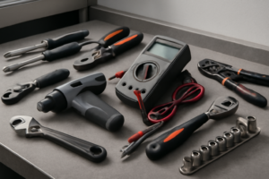
🔧 Required Tools
- 1/4″ nut driver
- Phillips screwdriver
✔️ Difficulty & Cost
Difficulty: Moderate
Estimated Cost: $30-60
✔️ Repair Steps
Step 1: Disconnect power
Disconnect Power
1. Locate your home’s main electrical panel (breaker box), typically found in the basement, garage, utility room, or exterior wall of your home.
2. Open the panel door by pulling the handle or releasing the latch on the front cover.
3. Identify the circuit breaker labeled for your kitchen range or oven. Look for labels reading “Range,” “Oven,” “Kitchen Range,” or a specific amperage rating of 40-50 amps. This breaker will be a double-pole breaker (two switches joined together, wider than standard breakers).
4. Flip the double-pole breaker to the OFF position by pushing the switch away from the center of the panel. You should feel a definite click, and the switch will move approximately 1/4 inch from its ON position.
5. Place a piece of masking tape over the breaker and write “DO NOT TURN ON – REPAIR IN PROGRESS” with a permanent marker. This prevents anyone from accidentally restoring power while you’re working.
6. Return to the range and verify power is disconnected by turning the oven control knob or pressing the oven control buttons. The display panel should be completely dark with no lights, numbers, or sounds.
7. Attempt to turn on a cooktop burner by rotating its control knob to HIGH. The burner should not heat up or show any red glow. Wait 30 seconds to confirm no heat develops.
8. Locate the oven light switch (usually on the control panel) and press it. The interior oven light should not illuminate.
9. Use a non-contact voltage tester (also called a voltage detector pen) to verify power is off. Touch the tester probe to the metal frame of the range near the control panel area. The tester should not beep or light up, indicating no voltage is present.
10. Pull the range away from the wall by gripping both sides of the unit approximately 12 inches from the front edges. Slide it forward 24-36 inches to access the rear panel where the power cord connects.
11. Look at the back lower section of the range where the power cord enters the unit through a metal conduit or strain relief connector. The power cord will have 3 or 4 thick wires (typically black, red, white, and sometimes green or bare copper for ground).
12. Use the non-contact voltage tester again at the point where the power cord enters the range. Touch the tester to the strain relief fitting and each visible wire section. The tester must remain silent and unlit, confirming zero voltage.
Troubleshooting This Step
**If the breaker won’t stay in the OFF position**: The breaker has tripped and locked. Push it fully to ON first, then immediately flip it to OFF.
**If the display still shows power after flipping the breaker**: You’ve turned off the wrong breaker. Return to the panel and look for another double-pole 40-50 amp breaker.
**If the voltage tester beeps at the power cord connection**: Power is still present. Return to the breaker panel and verify you turned off the correct breaker, or call an electrician.
Step 2: Remove control panel
Remove Control Panel
1. Locate the two Phillips-head screws at the front top edge of the control panel, positioned approximately 8 inches in from each side edge of the range. These screws are silver and recessed about 1/4 inch into the panel.
2. Using a Phillips-head #2 screwdriver, turn each screw counterclockwise 6-8 full rotations until completely removed. Set these screws aside in a container—you’ll need them for reassembly.
3. Grip the control panel at both top corners and pull the top edge forward approximately 2 inches. The panel will pivot at the bottom, creating a 30-degree angle.
4. Lift the entire panel upward about 1 inch while maintaining the forward angle. The panel will disengage from two metal tabs located at the bottom edge, approximately 10 inches apart.
5. Identify the wire harness bundle behind the control panel. You’ll see a cluster of 6-8 wires (typically including red, black, white, blue, and yellow wires) connected to the back of the control board with white plastic connectors.
6. Locate the main wire connector—a white rectangular plug approximately 2 inches wide with 6 wires entering it. This connector sits centered on the back of the control board.
7. Press the locking tab on the top of the white connector with your thumb while pulling the connector straight away from the control board. Apply firm pressure—the tab requires approximately 5 pounds of force to release. The connector will slide out approximately 1/2 inch when fully disconnected.
8. Identify the smaller secondary connector on the right side of the control board (if present on your model)—this is a 2-wire connector with one brown and one orange wire. Press the side tabs inward simultaneously and pull straight back to disconnect.
9. Set the control panel face-down on a clean towel on your countertop, allowing the wire harnesses to remain attached but hanging freely. Position the panel so wires aren’t kinked or under tension.
Troubleshooting This Step
**If the panel won’t lift after removing screws:** The bottom tabs may be stuck. Push the panel back flush against the range, then pull forward again while lifting simultaneously.
**If a wire connector won’t release:** Do not pull on the wires themselves. Locate the release tab—it’s always on the connector housing, never on the wires. Apply pressure to the tab while rocking the connector gently side-to-side, then pull straight back.
**If wires accidentally disconnect from the connector:** Note the wire positions before removing any wires. Wires insert into specific slots in the connector housing. Red wires typically occupy positions marked “L1” or “HOT,” black wires go to “L2” or “LOAD,” white wires connect to “N” or “NEUTRAL,” and green/yellow wires attach to ground terminals marked “GND” or with a ground symbol.
**Verification:** The control panel should now rest freely with wires still attached. Connectors should show no exposed metal pins—if you see brass or silver pins, the connector wasn’t fully removed and may damage during the next steps. Reconnect and try again.
Step 3: Disconnect switch wires (label them)
Disconnect Switch Wires (Label Them)
Wire Disconnection Sequence
1. Locate the oven selector switch, positioned on the right side of the control panel assembly, approximately 3 inches from the top edge and 2 inches from the right edge.
2. Identify the wire harness connected to the switch—you’ll see 6 wires in a white plastic connector block: two red wires, two black wires, one white wire, and one green wire.
3. Use a permanent marker or masking tape to create labels before disconnecting. Write “R1” on tape for the red wire in position 1 (leftmost terminal), “R2” for the red wire in position 2, “B1” for the black wire in position 3, “B2” for the black wire in position 4, “W” for the white wire in position 5, and “G” for the green wire in position 6 (rightmost terminal).
4. Press the white plastic locking tab on the connector block with your thumb while pulling the connector straight out with your other hand—apply 3-5 pounds of force until you hear a click and the connector releases.
5. If the connector block doesn’t release, insert a flat-head screwdriver (3/16-inch blade width) into the slot below the locking tab and pry upward 1/8 inch while pulling the connector.
6. For switches with individual spade connectors instead of a block connector: use needle-nose pliers to grip each spade connector at the plastic housing (not the wire), then pull straight off with 2-3 pounds of force.
7. If any wire pulls out of its terminal during disconnection, note the terminal position number (1-6, counting left to right) and wire color immediately.
Wire Color Functions – Red wires (R1, R2): Hot power lines from circuit board, delivering 240V – Black wires (B1, B2): Load wires to oven heating elements – White wire (W): Neutral return path – Green wire (G): Ground connection to metal chassis
Troubleshooting: If Wires Become Disconnected
8. If a wire pulls out of the connector block: examine the connector block and locate the empty terminal slot—match the wire color to the label you created.
9. Red wires connect only to terminals marked “L1” or “L2” on the switch body (stamped on the black plastic).
10. Black wires connect only to terminals marked “BAKE” or “BROIL” on the switch body.
11. White wire connects to the terminal marked “N” (neutral).
12. Green wire connects to the terminal marked with a ground symbol (three horizontal lines decreasing in length).
13. To verify correct wire placement before reconnecting: red and black wires should never share the same terminal position—they alternate in the connector block.
Connection Verification
14. After disconnection, inspect each wire end for damage—the metal terminal should be shiny and free of black carbon deposits.
15. If terminals show burn marks or melted insulation within 1/2 inch of the connector, trim the damaged section with wire strippers and crimp on a new spade terminal using a crimping tool.
16. Bend wires away from the switch body to prevent interference during switch removal—fold the wire bundle toward the front of the range and secure with a twist tie to the nearby metal bracket.
Step 4: Remove switch mounting
Remove Switch Mounting
1. Locate the two Phillips-head screws securing the selector switch to the rear panel bracket. These screws are positioned 2 inches apart, one at the top and one at the bottom of the switch housing.
2. Using a Phillips-head screwdriver #2, rotate the top mounting screw counterclockwise 8-10 full turns until it comes free. Place this screw in your parts container.
3. Support the selector switch body with your non-dominant hand while removing the bottom screw. Rotate counterclockwise 8-10 full turns until free. The switch will now be loose and held only by the wire connections you disconnected in the previous step.
4. Gently pull the switch housing straight back toward you approximately 3-4 inches away from the rear panel. You’ll now see the switch fully separated from its mounting bracket.
5. Examine the mounting bracket for any plastic tabs or clips. On this model, there are two gray plastic retention tabs on the left and right sides of the mounting hole. These tabs may catch on the switch body during removal.
6. If the switch body catches on the retention tabs, press each gray tab inward (toward the center) with your thumb while pulling the switch body backward. Each tab only needs to compress 1/8 inch to clear the switch housing.
7. Rotate the switch body clockwise 45 degrees if needed to angle it through the mounting bracket opening. The switch housing measures 2.5 inches wide, and the mounting hole is 2.75 inches wide, providing 1/8 inch clearance on each side.
8. Set the old selector switch aside on your work surface with the wire terminals facing up. Keep the switch oriented upright to prevent any internal components from shifting.
Troubleshooting This Step
**If screws won’t turn:** The screws may have threadlock compound. Apply downward pressure while turning to break the seal. If the screwdriver slips, the screw head may be partially stripped. Switch to a #3 Phillips screwdriver for better grip.
**If the switch won’t pull free after screw removal:** Check that both screws are completely removed, not just loosened. Verify no wires are still connected by visually inspecting all four terminal positions on the switch rear.
**If retention tabs break during removal:** The tabs are cosmetic retainers only. The screws provide the actual mounting security. Broken tabs won’t affect switch installation, but you may hear slight rattling during oven operation.
**If you dropped a mounting screw inside the control panel:** Tilt the range backward 15-20 degrees and shake gently. The screw should fall toward the access opening. Use a magnetic pickup tool or flashlight to locate it in the panel cavity.
**Verifying correct removal:** The switch housing should move freely in your hand with no resistance. All four wire terminal posts should be visible and empty. The mounting bracket should have two empty screw holes visible.
Step 5: Install new switch
Install New Switch
1. Remove the new oven selector switch from its packaging and orient it so the wire terminals face the rear of the range (toward the back wall where the wiring harness is located).
2. Position the new switch into the mounting bracket on the control panel, aligning the metal tabs on the switch body with the corresponding slots in the bracket opening (located approximately 8 inches from the left edge of the control panel).
3. Press the switch firmly into the bracket until you hear an audible click, indicating the mounting tabs have locked into place. The switch should sit flush with the front surface of the control panel with no gaps visible around the edges.
4. Locate the wire harness you set aside during removal. You will reconnect 6 wires in the following order from left to right as you face the back of the switch: – **Terminal 1 (leftmost)**: Brown wire (connects to bake element circuit) – **Terminal 2**: Red wire (connects to L1 hot/line power) – **Terminal 3**: Orange wire (connects to broil element circuit) – **Terminal 4**: Yellow wire (connects to oven light) – **Terminal 5**: Black wire (connects to L2 hot/line power) – **Terminal 6 (rightmost)**: White wire with blue stripe (connects to neutral/common)
5. Starting with Terminal 1, push the brown wire’s spade connector straight onto the terminal blade until it slides completely down and seats against the plastic terminal base. You should feel resistance for the first half-inch, then the connector will slide the remaining distance easily.
6. Repeat this process for each remaining wire in sequence (red, orange, yellow, black, white/blue), pushing each spade connector fully onto its corresponding terminal.
7. After all 6 wires are connected, perform this verification: Grip each wire individually 2 inches back from the connector and pull gently with 3-5 pounds of force (about the pressure needed to open a cabinet door). No wire should disconnect. If any wire pulls free, the spade connector was not fully seated—push it back on until it bottoms out against the terminal base.
8. Bundle the excess wire slack (approximately 4-6 inches) and secure it to the metal frame rail directly behind the switch using a nylon zip tie, leaving only 2 inches of wire exposed between the tie point and the switch terminals to prevent wire strain.
Troubleshooting Tips for This Step
**If a wire connector won’t slide onto the terminal:** The spade connector may be too narrow. Check that the connector opening measures 0.25 inches wide (1/4-inch blade size). If it’s narrower, you have the wrong connector—obtain a proper 1/4-inch female spade connector rated for 250V.
**If you’re unsure which wire goes where:** Match the wire color from your old switch to the new one. The terminal positions are identical on all Maytag MER6600FZ selector switches. Never cross-connect colors—red always connects to the second terminal from the left, black to the fifth position.
**If multiple wires came loose:** Look at the terminal blade width and position. Terminals 2 and 5 (red and black) typically have slightly wider blades than the others, making them identifiable by sight.
Step 6: Reconnect wires
Reconnect Wires to New Oven Selector Switch
Wire Identification You will see 6 wires connected to the new selector switch terminals: – **2 Red wires** (Line power – hot) – **2 Black wires** (Load power – hot) – **1 White wire** (Neutral) – **1 Green or bare copper wire** (Ground)
Reconnection Process
1. Locate the wire bundle you labeled or arranged during disassembly – it should be resting on the right side of the control panel cavity, approximately 4 inches from the switch mounting location.
2. Identify terminal L1 on the new selector switch – it’s the leftmost terminal on the back of the switch body, marked with “L1” in white lettering.
3. Connect the first red wire to terminal L1 by sliding the spade connector straight onto the terminal blade until it bottoms out – you’ll feel resistance when fully seated. The connector should cover the terminal blade completely with no exposed metal visible.
4. Connect the second red wire to terminal L2, located immediately to the right of L1. Push the spade connector on firmly until it clicks into position.
5. Locate terminals marked “BAKE” and “BROIL” on the switch – these are the center two terminals, with BAKE on the left and BROIL on the right.
6. Connect one black wire to the BAKE terminal and the other black wire to the BROIL terminal using the same firm pushing motion. Each connector should slide on with moderate resistance and click when fully engaged.
7. Connect the white (neutral) wire to the terminal marked “N” on the right side of the switch body, second from the end.
8. Connect the green or bare copper (ground) wire to the final terminal marked with a ground symbol (three horizontal lines decreasing in length). This terminal is at the far right edge of the switch.
9. Verify each connection by grasping each wire 1 inch behind the spade connector and pulling straight back with firm pressure – the connector should not slide off. If any connector pulls free, push it back on more firmly until you hear an audible click.
10. Position the wire bundle so wires drape naturally toward the bottom of the control panel cavity without sharp bends. Wires should not be stretched tight or compressed against any metal edges.
Verification and Troubleshooting
**How to verify connections are correct:** – Red wires connect only to L1 and L2 terminals (never to BAKE or BROIL) – Black wires connect only to BAKE and BROIL terminals – White wire connects only to N terminal – Ground wire connects only to ground terminal – No bare metal should be visible on any terminal blade after connection
**Common wire connection mistakes:** – Connecting red wires to BAKE/BROIL terminals will prevent oven from heating – Reversing neutral and ground creates a shock hazard – white always goes to N, green/bare always goes to ground symbol – Partially seated connectors will cause intermittent operation or arcing
**If a wire pulls off during verification:** Match the wire color to its original terminal location – red to L1/L2, black to BAKE/BROIL, white to N, ground to ground symbol.
📝 Next Steps: This post will be expanded by Claude AI with:
- Detailed step-by-step instructions with explanations
- Safety warnings and precautions
- Tool recommendations and usage tips
- Troubleshooting common issues
- Product recommendations (repair kits, tools) from Amazon via Firecrawl
- Affiliate links integrated naturally into sentence form
🔧 Recommended Parts & Tools
You can find the replacement part you need, such as this FZ31-9E 11 Pins 7 Positions FZ31-10 Oven Function Rotary Selector Switch Fits…, on Amazon. For this repair, you’ll need a KOKISO Microwave Oven Repair Replacement Parts Kits, KW3A Microwave Door Swit… which includes all the necessary components. You can find the replacement part you need, such as this YeMoMo 4D Double-Ended Eyebrow Pen, Hair-Like Brush Tip, Waterproof Brow Tint…, on Amazon. You can find the replacement part you need, such as this 74010750 Bake Element, on Amazon. You can find the replacement part you need, such as this Ismosm 4Pcs Nut Driver Set RC Tool Set Hex Nut Driver for RC Vehicle RC Helic…, on Amazon.
As an Amazon Associate, I earn from qualifying purchases.
How Much Does This Repair Cost?
DIY parts for this repair typically run $25–$55 depending on which selector switch you need. A professional appliance repair technician will usually charge $150–$250 total once you factor in the service call fee and labor.
Recommended Products
These are the parts and tools we recommend for this repair, based on compatibility and customer reviews:
- 7403P239-60 Upgraded Oven Range Infinite Switch Compatible With Whirlpool Maytag KitchenAid Jenn-Air Amana Magic Chef Admiral Norge Roper Replaces 7403P372-60 812675 AP6011291 NL812675 PS11744487
- ClimaTek Upgraded Oven Range Infinite Switch for Whirlpool, Maytag, Estate, Amana, Kenmore #s WP3148952, AP6007657, 3148952, 492438, PS11740774, WP3148952VP, 811715, 811701
- ForeverPRO 7403P181-60 Switch Inf. for Admiral Range 7403P181-60 1832-336 1832336 3325
- Choice Part 74011242 Burner Eye Switch Control for Maytag Jenn Air Electric Range
As an Amazon Associate, I earn from qualifying purchases.