🔩 RTD Temperature Sensor Repair Guide for GE Profile PT7550SFSS (Electric Wall Oven – Double)
💡 This repair guide will be expanded with detailed instructions. Claude AI will add comprehensive explanations, safety tips, troubleshooting advice, and product recommendations.
🔨 Pro Tip from Dave
On the PT7550SFSS, a common mistake is replacing the sensor without checking the sensor harness connector behind the oven cavity wall — corrosion on those pins mimics a failed WB21X10173 and will throw the same F3 code even with a brand-new sensor installed. Use your multimeter to confirm the sensor reads between 1,000–1,100 ohms at room temperature before assuming the part is bad.
🔍 Symptoms
Temperature inaccurate, F3 error code
🔧 Part Numbers
- WB21X10173
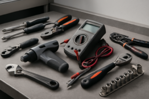
🔧 Required Tools
- 1/4″ nut driver
- multimeter
✔️ Difficulty & Cost
Difficulty: Easy
Estimated Cost: $20-40
✔️ Repair Steps
- Step 2: Disconnect power
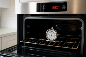
Step 1: Test sensor (should be ~1100 ohms at room temp)
Test RTD Temperature Sensor (Target: ~1100 Ohms at Room Temperature)
Testing Procedure
1. Unplug the oven completely from the wall outlet or turn off the circuit breaker dedicated to this oven at your electrical panel. Verify power is off by attempting to turn on the oven – the display should be completely dark.
2. Open both oven doors fully to access the interior cavities.
3. Locate the RTD sensor in the upper oven cavity – it’s a thin metal probe (approximately 1/8 inch diameter, 6-8 inches long) protruding through the upper left rear wall, approximately 3 inches down from the top and 2 inches from the left side.
4. Set your digital multimeter to the ohms (Ω) setting, specifically the 2000-ohm range. If your meter has an auto-ranging feature, simply select the ohms symbol.
5. Look at the sensor probe tip inside the oven – you’ll see where it enters through a small grommet in the rear wall. Trace this back 12-14 inches behind the oven cavity where it terminates in a 2-wire connector.
6. Pull the oven forward 6-8 inches from the wall to access the back panel area. You may need assistance as double ovens weigh 150-200 pounds.
7. Locate the wire connector at the end of the RTD sensor probe coming from the upper oven. It’s a white plastic 2-pin connector with two wires: typically one red and one white (or two wires of the same color, often white or gray).
8. Disconnect the 2-pin connector by pressing the locking tab (a small rectangular protrusion on one side) while pulling the connector halves apart. The connector separates into a male and female end.
9. Identify which connector half has the wires going directly to the sensor probe (this is the sensor side). The other half has wires going to the control board.
10. Touch one multimeter probe to each of the two metal terminals on the sensor side of the connector. Polarity doesn’t matter for resistance testing.
11. Read the ohm measurement on your multimeter display. At room temperature (68-72°F), the reading should be between 1050-1150 ohms. A reading of 1100 ohms ±50 ohms indicates a functional sensor.
Troubleshooting This Step
**If you get an “OL” (overload) or infinite resistance reading:** The sensor has an internal break and must be replaced. This is the most common failure mode.
**If you get a reading below 1000 ohms or above 1200 ohms:** The sensor is drifting out of specification and will cause temperature inaccuracies. Replacement is recommended.
**If you get zero ohms or near-zero resistance:** The sensor is shorted internally and must be replaced immediately.
**If the connector is difficult to separate:** The locking tab is located on the narrow side of the white connector body. Press it firmly toward the connector center while pulling straight apart – do not twist or rock the connector.
**If wires pull out of the connector during disconnection:** Note which terminal position each wire occupied (left or right when viewing the connector). RTD sensors are non-polarized, so either wire can connect to either terminal, but they must reconnect to the same control board wires they were originally attached to.
Step 2: Disconnect power
Disconnect Power
1. Locate your home’s main electrical service panel (breaker box), typically found in the basement, garage, utility room, or exterior wall.
2. Open the breaker panel door by lifting or swinging it outward.
3. Identify the circuit breaker(s) for your wall oven. The GE Profile PT7550SFSS double oven requires two dedicated 30-amp double-pole breakers (a total of 4 breaker switches—2 per oven cavity). Look for breakers labeled “Wall Oven,” “Oven,” or “Kitchen Appliance.” Each double-pole breaker will have two switches connected by a bridge or handle tie.
4. Switch OFF the first double-pole breaker by flipping both connected switches to the OFF position (toward the outside edge of the panel). You’ll feel resistance—push firmly until both switches are fully in the OFF position.
5. Switch OFF the second double-pole breaker the same way, ensuring both switches move completely to OFF.
6. Return to the oven location with a non-contact voltage tester (also called a voltage detector pen).
7. Open both oven doors fully to access the interior cavities.
8. Press the control panel touchpad or turn any knobs. The display screen should be completely dark with no lights, sounds, or response. If anything illuminates or responds, return to the breaker panel and verify you’ve switched off the correct breakers.
9. Use the non-contact voltage tester to verify power is off at the junction box. The junction box is located at the top rear of the oven cavity (you’ll need to reach into the upper oven compartment). Hold the tester tip within 1 inch of any visible wire connections—the tester should NOT light up or beep. If it does, you have not disconnected the correct breaker.
10. Test the voltage tester on a known live outlet to confirm it’s working properly before proceeding.
**Troubleshooting Tips:**
– **If you cannot identify the correct breakers**: Switch off all breakers labeled for kitchen appliances, then verify the oven display is dark. Test breakers one at a time until the display goes off.
– **If the oven shares a circuit with other appliances**: This is a code violation for this model, which requires dedicated circuits. Proceed with the repair but contact a licensed electrician afterward to install proper dedicated circuits.
– **If your breaker panel has fuses instead of breakers**: Remove the two 30-amp fuses by pulling them straight out using the fuse puller tool attached to the panel door. The fuses are cylindrical, approximately 2 inches long.
– **If the voltage tester beeps at the junction box**: Do NOT proceed. Return to the breaker panel and switch off additional breakers until the tester shows no voltage. Mark the correct breakers with masking tape for future reference.
– **If you have no voltage tester**: Purchase one before continuing—they cost
0-20 at hardware stores. Visual confirmation alone is insufficient for electrical safety.
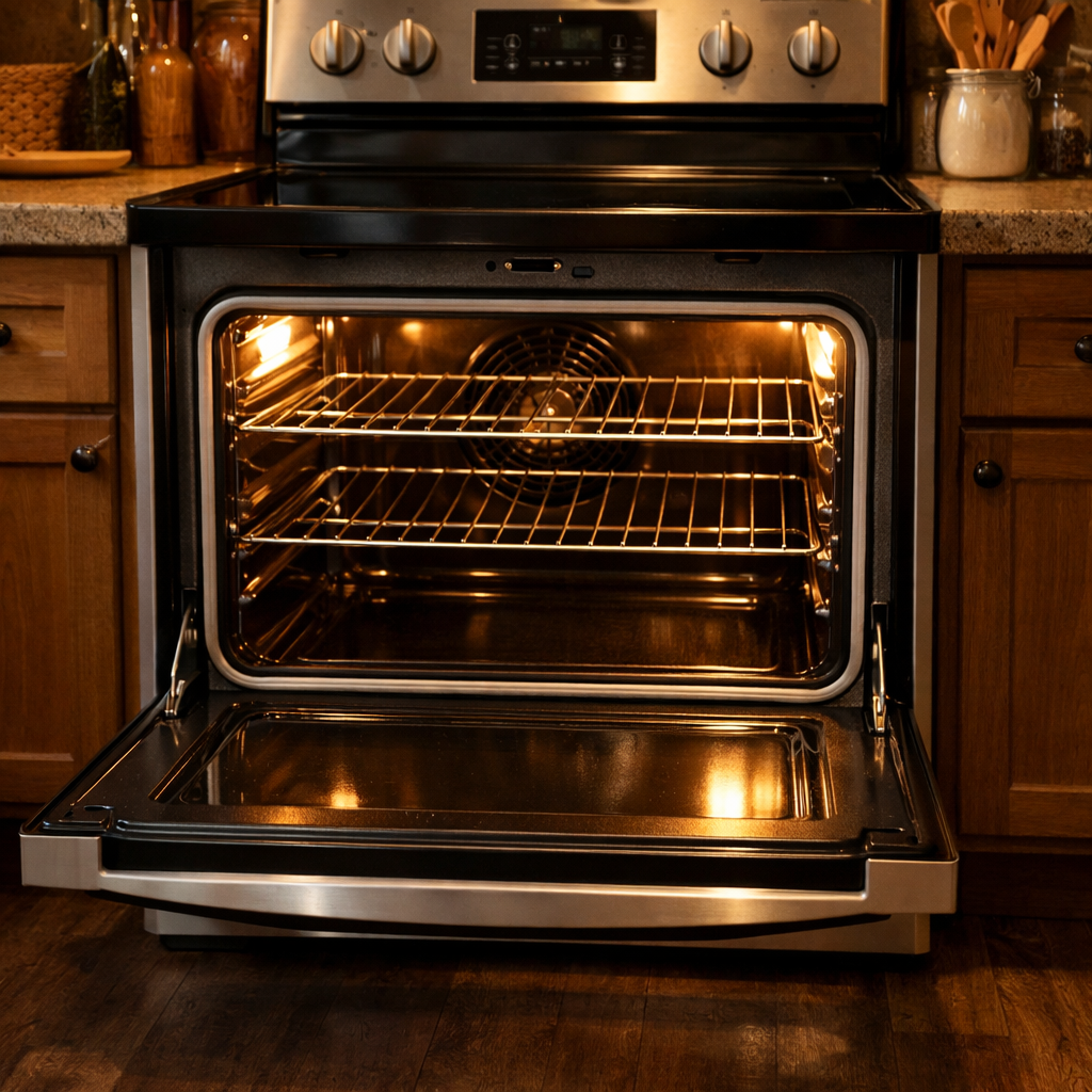
Step 3: Remove oven racks
Remove Oven Racks
1. Open the upper oven door fully until it stops at its maximum open position (approximately 90 degrees from closed).
2. Locate the two oven racks inside the upper cavity—one positioned in the middle slot and one in the lower slot, approximately 4 inches apart vertically.
3. Starting with the middle rack, grasp it firmly with both hands at the front edge, one hand on each side.
4. Pull the rack straight toward you approximately 6 inches until you feel it stop—this is the safety stop position that prevents the rack from sliding out accidentally during normal use.
5. Lift the front edge of the rack upward approximately 1 inch to disengage it from the rack guides on both sides of the oven cavity.
6. Continue pulling the rack straight out while maintaining the slight upward angle until it clears the oven cavity completely.
7. Set the rack aside on a clean, flat surface away from your work area.
8. Repeat substeps 3-7 for the lower rack in the upper oven cavity.
9. Open the lower oven door fully until it stops at its maximum open position.
10. Locate the two oven racks inside the lower cavity, positioned similarly to the upper oven.
11. Grasp the middle rack with both hands at the front edge and pull it straight toward you approximately 6 inches until it reaches the safety stop.
12. Lift the front edge upward approximately 1 inch to clear the rack guides, then pull the rack completely out of the cavity.
13. Set this rack aside with the others.
14. Remove the final rack from the lower oven using the same pull-lift-remove technique.
15. Verify all four racks are removed by visually inspecting both oven cavities—you should see empty rack guide slots on both sidewalls of each cavity.
Troubleshooting Tips for This Step:
**If a rack won’t slide forward past the safety stop:** Push the rack back in 2 inches, then lift the front edge higher (approximately 2 inches instead of 1 inch) while pulling forward. The safety stop mechanism requires sufficient upward angle to disengage.
**If a rack catches or binds while pulling out:** The rack may be misaligned in the guides. Push it back in completely until both sides are seated evenly, then pull straight out without twisting or angling to one side.
**If rack guides appear bent or damaged:** You can still proceed with the repair, but note that rack guides may need replacement after completing the RTD sensor repair. Bent guides will not affect access to the sensor mounting location.
**Why racks must be removed:** The RTD sensor is mounted on the upper left rear wall of each oven cavity. Racks obstruct access to this area and create risk of damaging the sensor wire during removal if they remain installed. Additionally, racks can interfere with your hand positioning when reaching into the cavity to disconnect the sensor connector located behind the rear panel.
Step 4: Remove sensor bracket screw
Remove Sensor Bracket Screw
1. Locate the RTD sensor bracket at the top left corner of the upper oven cavity, approximately 3 inches from the left side wall and 2 inches down from the top edge.
2. Identify the single Phillips-head screw (size #2) securing the metal bracket to the oven cavity wall. The screw is approximately 3/4 inch long with a silver finish.
3. Check for wire obstruction: You’ll see two wires (one red and one white) running from the RTD sensor probe through a white ceramic insulator. These wires exit the bracket and route downward toward the control board area.
4. Push the wire bundle approximately 1 inch to the right, away from the screw head, to create clearance for your screwdriver. The wires have enough slack to move without disconnecting.
5. Insert your Phillips #2 screwdriver into the screw head and turn counterclockwise. Apply firm downward pressure (approximately 5-10 pounds of force) while turning to prevent the screwdriver from slipping out of the screw head.
6. Remove the screw completely, turning it 8-10 full rotations. Place the screw in a container immediately—this specific screw has a flat washer permanently attached underneath the head.
7. Hold the bracket with your left hand while removing the screw with your right hand. The bracket may shift slightly as the screw loosens, but it should remain in position until you physically move it.
8. Once the screw is out, observe that the bracket is now loose but still positioned around the RTD sensor probe. The probe itself (a thin metal tube approximately 4 inches long) extends through the bracket and into the oven cavity.
9. Set the removed screw on a clean work surface where you can retrieve it during reassembly. The washer must remain on the screw—do not separate them.
Troubleshooting Tips for This Step
**If the screw won’t turn**: The screw may have thread-locking compound applied at the factory. Apply firm downward pressure and use short, controlled turns rather than continuous rotation. The compound will break free after the first quarter-turn.
**If the screwdriver slips from the screw head**: The screw head may have paint or debris in the slots. Use a wire brush or the corner of a paper towel to clean out the screw head slots before attempting again.
**If the wires prevent access**: Do not force the screwdriver at an angle. Instead, use your free hand to hold both wires against the right side of the oven cavity wall while you work. The wires can bend approximately 45 degrees without damage.
**If the bracket falls when the screw is removed**: This is normal. Catch the bracket with your left hand. The sensor probe will remain in place—it’s not attached to the bracket permanently, only positioned through it.
**If you drop the screw into the oven cavity**: Use a telescoping magnetic pickup tool or a piece of duct tape on your finger to retrieve it from the bottom of the cavity. The screw must be reused during reassembly as it includes the correct washer size for proper grounding.
Step 5: Pull sensor out, disconnect from back
Pull Sensor Out and Disconnect from Back
1. Grasp the RTD sensor probe at the metal mounting bracket (the 3-inch wide metal plate you loosened in Step 4), not at the thin sensor wire itself, which can break if pulled.
2. Pull the sensor straight back toward you with steady pressure – it will slide out approximately 6-8 inches through the rubber grommet in the oven cavity wall. The sensor probe is a thin metal rod about 1/4 inch diameter.
3. Continue pulling until you see the wire connector emerge from inside the oven wall. The connector is a white plastic rectangular plug approximately 1 inch long, located 2-3 inches behind where the sensor enters the wall.
4. Identify the 2-wire connector: You’ll see 2 wires (typically both white or one white and one red) running from the sensor probe into the white plastic connector housing. These are low-voltage sensor wires, not high-voltage power wires.
5. Locate the mating connector on the oven’s wire harness – it’s the matching white plastic female connector with 2 wires (colors may be white, red, or blue) attached to a wire bundle running along the inside of the oven wall.
6. Grip the white plastic connector bodies (not the wires) with your thumb and forefinger on each hand, one hand on each side of the connection point.
7. Pull the two connector halves straight apart using a rocking motion – wiggle side-to-side slightly while pulling to release the internal friction tabs. Apply 5-10 pounds of force; the connectors will separate with a slight pop.
8. If the connector resists, look for a locking tab on one side of the white plastic housing. Press the tab down with your thumbnail while pulling the connectors apart.
9. Once disconnected, examine both connector halves: You’ll see 2 metal pins on one side and 2 metal sockets on the other. Check that no pins are bent.
10. Pull the entire RTD sensor assembly completely free from the oven – you now have the sensor probe, wires, and one connector half in your hand.
Troubleshooting Tips for This Step
**If the sensor won’t slide out**: The rubber grommet may have seized. Apply a drop of dish soap around the sensor where it enters the grommet, wait 30 seconds, then twist the sensor gently while pulling to break the seal.
**If wires become disconnected from the sensor connector**: The RTD sensor wires are not color-coded for polarity – either wire can connect to either terminal on the sensor. Reconnect both wires to the 2-pin connector on the sensor end; orientation doesn’t matter for resistance-based sensors.
**If you accidentally disconnect wires from the oven harness connector**: Match the wire colors – white to white, red to red, or blue to blue. If all wires are the same color, either orientation works since RTD sensors have no polarity.
**Common mistake**: Pulling on the thin sensor wires instead of the connector bodies. This can separate wires from connector terminals internally. Always grip the plastic connector housings.
**Verification**: Examine the sensor probe tip – it should be smooth and metallic without cracks or burn marks, which would indicate a failed sensor.
Step 6: Install new sensor at same depth
Install New Sensor at Same Depth
1. Hold the new RTD sensor with the metal probe pointing toward the oven cavity opening where you removed the old sensor.
2. Locate the mounting hole in the rear wall of the oven cavity – this is a circular opening approximately 3/8 inch in diameter, positioned at the same location where the old sensor was removed.
3. Insert the metal probe end of the new sensor straight into the mounting hole, pushing it through until you feel slight resistance from the insulation on the back side of the oven wall.
4. Continue pushing the sensor probe inward, measuring the insertion depth against the reference mark you made on the old sensor (or if you noted the measurement, insert to exactly 2-1/4 inches from the white ceramic mounting bushing to the interior oven wall surface).
5. Stop pushing when the white ceramic bushing at the base of the sensor probe sits flush against the interior oven wall surface – the bushing should make full contact with no gap visible.
6. While holding the sensor probe at this depth with one hand, use your other hand to locate the mounting bracket or spring clip that secures the sensor from behind the oven wall (accessed through the service panel opening you used earlier).
7. Position the spring clip or mounting bracket over the white ceramic bushing, aligning the clip’s grooves with the raised ridges on the bushing exterior.
8. Press the clip firmly onto the bushing until it snaps into place – you will hear an audible click and feel the clip lock securely.
9. Tug gently on the sensor wire from behind the service panel – the sensor probe should not move more than 1/16 inch forward or backward if properly secured.
10. Route the sensor wire leads back through the same path the old sensor wires followed, keeping them away from any sharp metal edges or hot surfaces near the heating elements.
11. Reconnect the two sensor wires to the control board connector you disconnected earlier – the RTD sensor wires are typically both white or one white and one red, and they connect to a 2-pin connector (wire color order doesn’t matter for RTD sensors as they are non-polarized resistance devices).
12. Push the connector firmly onto the control board pins until it clicks and seats completely – no metal pins should be visible above the connector housing.
Troubleshooting: Installation Issues
**If the sensor won’t stay at the correct depth:** The spring clip is not fully engaged on the ceramic bushing. Remove the sensor, inspect the bushing for the two raised ridges (one on each side), and ensure the clip grooves align with these ridges before pressing down firmly.
**If the sensor probe slides too far into the oven cavity:** You’ve pushed it past the 2-1/4 inch mark. Pull it back out 1/4 inch at a time until the ceramic bushing sits flush against the interior wall, then resecure the spring clip.
**If you see a gap between the bushing and the wall:** The sensor is not inserted deep enough. Push the probe deeper while checking that the spring clip hasn’t caught on the back of the wall prematurely.
**To verify correct installation:** Look inside the oven cavity – you should see 2-1/4 inches of exposed metal probe extending into the cavity with the white ceramic bushing flush against the wall.
📝 Next Steps: This post will be expanded by Claude AI with:
- Detailed step-by-step instructions with explanations
- Safety warnings and precautions
- Tool recommendations and usage tips
- Troubleshooting common issues
- Product recommendations (repair kits, tools) from Amazon via Firecrawl
- Affiliate links integrated naturally into sentence form
🔧 Recommended Parts & Tools
You can find the replacement part you need, such as this 7“ RTD Temperature Probe Sensor, Replacement for Traeger Grill Probe, Interna…, on Amazon. For this repair, you’ll need a FCCUM RTD RTD Temperature Probe Sensor Grill, Replacement Parts for Traeger D… which includes all the necessary components. You can find the replacement part you need, such as this Amazon Business American Express Card, on Amazon. You can find the replacement part you need, such as this Ismosm 4Pcs Nut Driver Set RC Tool Set Hex Nut Driver for RC Vehicle RC Helic…, on Amazon. A Klein Tools MM325 Multimeter, Digital Manual-Ranging 600V AC/DC Voltage Teste… is essential for completing this repair safely and efficiently.
As an Amazon Associate, I earn from qualifying purchases.
How Much Does This Repair Cost?
The replacement RTD sensor WB21X10173 typically runs $20–$40 for DIY repair, including any basic tools you may need. A professional appliance technician will generally charge $120–$200 total once you factor in the service call fee and labor, making this one of the best bang-for-your-buck DIY repairs on this model.