🔩 Door Lock Motor Assembly Repair Guide for GE Profile PT7550SFSS (Electric Wall Oven – Double)
💡 This repair guide will be expanded with detailed instructions. Claude AI will add comprehensive explanations, safety tips, troubleshooting advice, and product recommendations.
🔨 Pro Tip from Dave
On the PT7550SFSS, before you condemn the motor entirely, check the wiring harness connector at the lock assembly — it’s notorious for heat-induced corrosion that mimics a dead motor. A lot of techs reflexively order WB14X25890 when WB14X24788 is actually the correct superseding part for later builds; always verify your serial number prefix. Also, never run a test self-clean cycle immediately after reinstalling — let the oven cool completely or you risk binding the new latch right away.
🔍 Symptoms
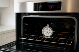
F9 error, door won’t unlock after self-clean, won’t lock
🔧 Part Numbers
- WB14X25890
- WB14X24788
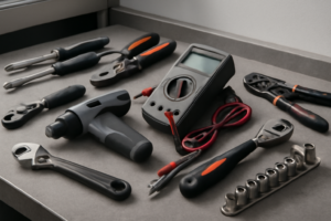
🔧 Required Tools
- 1/4″ nut driver
- Phillips screwdriver
✔️ Difficulty & Cost
Difficulty: Moderate
Estimated Cost: $80-150
✔️ Repair Steps
Step 1: Disconnect power
Disconnect Power
1. Locate your home’s electrical panel (breaker box), typically found in the basement, garage, utility room, or exterior wall.
2. Open the breaker panel door and identify the breaker labeled “Wall Oven,” “Double Oven,” or “Range.” GE Profile double wall ovens typically use a dedicated 240-volt double-pole breaker (two switches joined together with a connecting bar).
3. Switch the double-pole breaker to the OFF position by pushing both toggle switches away from the center of the panel until they click into the OFF position.
4. Place a piece of red electrical tape across the breaker switches and write “DO NOT TURN ON – REPAIR IN PROGRESS” on the tape. This prevents someone from accidentally restoring power while you’re working.
5. Return to the oven and attempt to turn on the upper oven by pressing the power button on the control panel. The display should remain completely blank with no lights, sounds, or display activity.
6. Press and hold any other control buttons for 3 seconds. Nothing should illuminate or respond.
7. Open the lower oven door and press the interior light switch (small button located on the upper left inside the oven cavity, approximately 2 inches from the top edge). The light should not turn on.
8. Verify complete power disconnection by testing both oven cavities’ interior lights and all control panel functions. All should be completely non-responsive.
Troubleshooting Tips for This Step
**If the control panel still shows power after switching the breaker:** – You may have switched the wrong breaker. Return to the panel and switch OFF additional breakers labeled “Kitchen,” “Appliances,” or any unlabeled breakers serving the kitchen area. – Test the oven again after switching each breaker until the display goes completely dark. – Some homes have a secondary disconnect box near the oven itself, typically a gray metal box mounted on the wall within 6 feet of the appliance.
**If you cannot identify the correct breaker:** – Switch breakers OFF one at a time, testing the oven display between each attempt. – Alternatively, switch OFF the main breaker (largest breaker at the top of the panel, usually 100-200 amps) to disconnect all power to the home, then proceed immediately with the repair.
**If someone else is home during the repair:** – Inform all household members that power is disconnected and lock the breaker panel if possible. – Keep the panel key with you to prevent accidental power restoration.
**Verifying successful disconnection:** – Zero lights on control panel = successful disconnection – Any blinking, dim lights, or partial display = power still connected, do not proceed
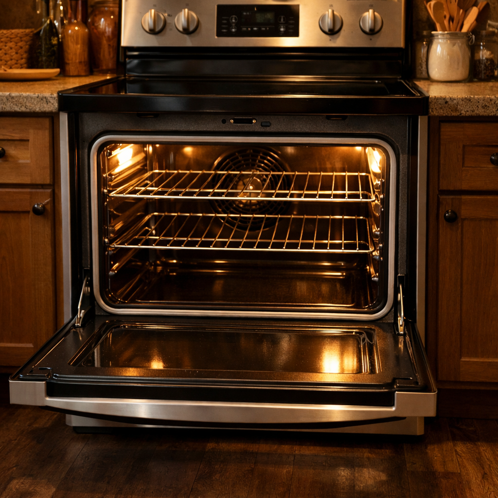
Step 2: Remove door (if easier access needed)
Remove Door (If Easier Access Needed)
**When to remove the door:** If you’re accessing the door lock motor assembly from the front or if the oven door limits your ability to reach the top of the oven cavity, remove the door. Skip this step if you can comfortably access the lock mechanism with the door open.
Door Removal Steps
1. Open the oven door fully to approximately 90 degrees from the closed position.
2. Locate the two door hinges on the left and right sides at the bottom of the oven opening where the door meets the oven frame.
3. Identify the hinge locks—these are small metal levers or clips positioned on the inner face of each hinge, measuring approximately 1 inch long and angled at 45 degrees.
4. Rotate the left hinge lock upward and forward approximately 90 degrees until it stops—you’ll feel resistance when it reaches the fully locked position. The lock will now be pointing toward you rather than lying flat against the hinge.
5. Repeat step 4 for the right hinge lock, rotating it upward and forward 90 degrees until it stops.
6. Close the oven door slowly to approximately 45 degrees (halfway between fully open and fully closed)—this is the release angle where the hinges disengage.
7. Grip the door firmly on both the left and right edges with both hands, positioning your fingers on the outer sides and thumbs on the inner sides.
8. Lift the door straight up approximately 1 inch while maintaining the 45-degree angle—you’ll feel the hinges release from their slots.
9. Once the hinges clear the slots, pull the door toward you while continuing to lift slightly, removing it completely from the oven frame.
10. Set the door face-down on a padded surface (folded towels work well) to prevent scratching the glass or control panel.
Troubleshooting This Step
**If the door won’t lift out:** The hinge locks are not fully rotated. Return the door to the fully open position and verify both hinge locks are rotated 90 degrees forward. You should see the locks pointing directly at you, not angled downward.
**If one side lifts but the other catches:** The door is not at the correct 45-degree angle. Adjust the door angle slightly more open or closed until both hinges release simultaneously.
**If the hinge locks won’t rotate:** They may be corroded. Apply penetrating oil (WD-40) to the pivot point, wait 5 minutes, then try rotating again using needle-nose pliers for additional leverage.
**If you accidentally let the door close with hinge locks engaged:** Do NOT force the door open. Reach inside the oven cavity from below, push the hinge locks back down to their flat position, then open the door normally.
Door Weight Warning
The door weighs approximately 25-30 pounds. Use both hands and maintain a secure grip throughout removal to prevent dropping.
Step 3: Remove motor cover plate
Remove Motor Cover Plate
1. Locate the motor cover plate on the left side of the oven cavity, approximately 8 inches down from the top of the upper oven chamber and 2 inches from the left wall. The cover is a rectangular metal plate measuring roughly 4 inches wide by 6 inches tall with a silver or white finish.
2. Identify the 2 Phillips-head screws securing the cover plate. These screws are located at the top and bottom edges of the plate, centered horizontally, spaced approximately 5 inches apart.
3. Using a Phillips-head #2 screwdriver, turn the top screw counterclockwise 8-10 complete rotations until it’s completely removed. Place the screw in your container immediately.
4. Support the cover plate with your free hand while removing the bottom screw. Turn counterclockwise 8-10 complete rotations until fully removed. The plate will become loose once this screw is out.
5. Pull the cover plate straight outward away from the oven wall approximately 1 inch, then tilt the bottom edge out slightly to clear any internal tabs or catches.
6. Set the cover plate aside with the screws. You’ll see the door lock motor assembly now exposed behind where the plate was mounted.
7. Inspect the wire bundle running from the top of the motor assembly. You’ll see 4 wires in this bundle: one white wire (neutral), one black wire (hot/load), one red wire (hot/line), and one green or bare copper wire (ground). These wires run upward toward the oven control board and may partially obstruct access to the motor mounting bracket.
8. If the wire bundle blocks access to the motor mounting screws, gently push the bundle approximately 1-2 inches toward the back of the oven cavity. Do not pull downward or sideways with force as these wires are connected to the control board above and excessive tension can damage the connections.
9. Secure the wire bundle in the moved position by wrapping a single-use zip tie loosely around the bundle and attaching it to the nearby metal frame bracket located 3 inches behind the motor. Leave enough slack so wires aren’t under tension—you should be able to slide your finger between the wire and the point where it enters the motor connector.
Troubleshooting Tips for This Step:
**If screws won’t turn easily:** The threads may have thread-locking compound. Apply firm downward pressure while turning to break the seal. If still stuck after 5 seconds of pressure, the screw head may be stripped—use a screw extractor bit or rubber band method (place rubber band over screw head before inserting screwdriver).
**If the cover plate won’t pull free after screw removal:** There may be paint or sealant bonding it to the frame. Insert a flathead screwdriver into the gap at the bottom edge and gently pry outward 1/8 inch, then try pulling again.
**If wires accidentally disconnect from motor:** Match wire colors to motor terminals: white wire to white/neutral terminal, black to black terminal, red to red terminal, green/bare to ground screw. Terminals are clearly marked on the motor housing.
Step 4: Disconnect wires
Disconnect Wires from Door Lock Motor Assembly
1. Locate the wire harness connector on the door lock motor assembly—it’s a white plastic rectangular connector approximately 1 inch wide, positioned on the right side of the motor body where the wires enter.
2. Identify the 3 wires entering this connector: one black wire (hot/power), one white wire (neutral), and one green or bare copper wire (ground). These wires come from the main oven wiring harness located along the left side of the cavity.
3. Press the locking tab on top of the white connector housing with your thumb while simultaneously pulling the connector straight away from the motor. The tab is a small rectangular protrusion centered on the connector’s top surface. Apply firm pressure—approximately 5 pounds of force—until you feel the tab release with a click.
4. Pull the connector 2-3 inches away from the motor to create working clearance. The wires will remain attached to the connector body.
5. Examine the motor’s wire terminals now visible where the connector was attached. You’ll see 3 metal blade terminals: the center terminal connects to black (hot), the left terminal connects to white (neutral), and the right terminal connects to green/ground.
6. Look for a secondary ground wire—a separate green or bare copper wire attached to the motor housing with a green grounding screw (8mm hex head). This ground wire runs from the motor body to the oven frame.
7. Use a 5/16-inch nut driver or socket to remove the green grounding screw by turning counterclockwise 4-5 full rotations until the screw and ring terminal come free. Set the screw aside in a container.
8. Move the disconnected wire harness to the left side of the work area, draping it over the top oven cavity edge to prevent it from falling into the cavity or interfering with motor removal.
Troubleshooting: What If Wires Become Disconnected?
**If individual wires pull out of the white connector housing:** – Match wire colors to terminal positions: black wire goes to center terminal, white to left terminal, green to right terminal. – Insert the wire’s metal terminal into the corresponding slot in the connector housing until it clicks into place. – Tug each wire with 2-3 pounds of force—none should pull free if properly seated.
**If you’re unsure which wire goes where:** – Black wires ALWAYS connect to hot terminals (center position on this motor). – White wires ALWAYS connect to neutral terminals (left position). – Green or bare copper wires ALWAYS connect to ground terminals (right position) or mounting screws. – Never connect black to white terminals, or white to black terminals—this will cause electrical failure.
**Verification check:** – Gently tug each wire at the connector. Resistance indicates proper connection. – Inspect the ground screw connection point on the motor housing—it should show a clean metal surface where the ring terminal sat. – The main connector should separate completely without any wires remaining attached to motor terminals.
Step 5: Remove motor mounting screws
Remove Motor Mounting Screws
1. Locate the two Phillips-head mounting screws securing the door lock motor assembly to the oven frame. These screws are positioned on the left side of the motor body, approximately 2 inches apart vertically.
2. Identify the wire harness connected to the motor. You’ll see a 6-wire connector bundle with wires in the following colors: red (hot/line power), black (hot/load power), white (neutral), yellow (motor control signal), blue (position sensor signal), and green with yellow stripe (ground).
3. Check if the wire bundle is blocking access to the upper mounting screw. If the wire harness crosses over the screw head, grasp the wire bundle where it exits the motor (approximately 1 inch from the connector) and gently push it downward toward the lower mounting screw, creating clearance.
4. Use a Phillips-head #2 screwdriver to remove the upper mounting screw. Turn counterclockwise approximately 8-10 full rotations. The screw is 1 inch long with a pan head. Set this screw aside in your labeled container.
5. Remove the lower mounting screw using the same Phillips-head #2 screwdriver, turning counterclockwise 8-10 full rotations. This screw is identical to the upper screw (1 inch, pan head).
6. Support the motor assembly with your non-dominant hand while removing the second screw, as the motor will become loose and may tilt forward once both screws are removed. The motor weighs approximately 1.5 pounds.
7. Once both screws are removed, the motor will still be attached via the wire harness connector. Do not pull on the motor housing yet—the wires are under slight tension from the harness routing through the door cavity.
Troubleshooting Tips for This Step
**If a screw won’t turn:** The screws may have thread-locking compound. Apply firm downward pressure while turning to prevent stripping the screw head. If the screw still resists, use a #3 Phillips screwdriver for additional torque.
**If the wire bundle prevents screw access:** Instead of pushing wires downward, you can temporarily disconnect the wire harness connector (where all 6 wires meet the motor body). Press the locking tab on the connector and pull straight away from the motor. This provides complete access to both screws, but you must reconnect before testing.
**If you accidentally disconnect the wire harness:** The connector only fits one way. Align the rectangular connector with the motor terminal, ensuring the locking tab faces upward. Push firmly until you hear a distinct click. Verify connection by gently tugging the connector—it should not pull free.
**If a screw falls into the door cavity:** Tilt the oven door back slightly (opening it wider) and shake gently. The screw should slide toward the hinge area where you can retrieve it. Use a magnetic pickup tool if available.
**Screw length verification:** Both mounting screws must be exactly 1 inch long. Using longer screws during reassembly will puncture the door insulation; using shorter screws will result in motor looseness and operational failure.
Step 6: Install new motor
Install New Door Lock Motor Assembly
1. Remove the new door lock motor assembly from its packaging and verify it matches the old part by comparing the mounting bracket shape, wire harness connector type (4-pin white plastic connector), and overall dimensions.
2. Hold the new motor assembly with the wire harness positioned on the left side and the metal mounting bracket facing toward you.
3. Align the two mounting holes on the motor bracket with the threaded holes in the oven door frame, located at the top center of the door, approximately 2 inches from the top edge and centered horizontally.
4. While holding the motor in position, insert the first 1/4-inch hex head screw (silver-colored) into the right mounting hole and thread it by hand 2-3 turns to hold the motor in place.
5. Insert the second 1/4-inch hex head screw into the left mounting hole and thread it by hand 2-3 turns.
6. Using a 1/4-inch nut driver or socket wrench, tighten the right screw until snug, then the left screw until snug—do not overtighten as the mounting bracket is aluminum and can strip. The screws should be firm but should require only moderate hand pressure to tighten.
7. Locate the wire harness connector extending from the new motor (white plastic housing with 4 wires: red, black, white, and yellow/green).
8. Locate the mating connector from the oven’s wiring harness, which should be resting near the motor mounting location with the same 4-wire configuration.
9. Align the white plastic connectors so the tab on one connector faces the slot on the other connector—the connectors are keyed and will only fit one way.
10. Push the connectors together firmly until you hear and feel an audible click, indicating the locking tab has engaged. The connection point should show no gap between the two connector housings.
11. Gently tug on both sides of the connector with 2-3 pounds of force—the connector should not separate if properly locked.
12. Route the wire harness slack along the right side of the door frame, tucking it behind the metal retaining clip located 4 inches below the motor assembly to prevent the wires from interfering with the door mechanism.
Troubleshooting for This Step
**If the motor won’t align with mounting holes:** The motor may be rotated 180 degrees. Flip it so the wire harness is on the opposite side.
**If the connector won’t click together:** Check that you’re aligning the keyed tab correctly. The tab on one connector should face upward while the slot on the mating connector faces downward. Rotate one connector 180 degrees if they won’t mate.
**If wires become loose from the connector:** The individual wire terminals inside the white plastic housing can be reinserted. Use needle-nose pliers to push each wire terminal back into its position until it clicks—red wire goes to position 1 (marked on connector housing), black to position 2, white to position 3, yellow/green to position 4.
**If the connector separates easily after connecting:** The locking tab may not be fully engaged. Disconnect and reconnect, applying more pressure until a distinct click is heard.
Step 7: Test lock operation
Test Lock Operation
1. Locate the circuit breaker labeled for your wall oven and flip it to the ON position to restore power to the unit.
2. Press the control panel power button on the upper oven. The display should illuminate, showing the current time or default screen.
3. Locate the oven door lock button on the control panel, typically labeled with a padlock icon or “DOOR LOCK” text. Press and hold this button for 3 seconds.
4. Listen for the lock motor engaging. You should hear a distinct whirring or grinding sound lasting 5-8 seconds as the motor drives the lock mechanism into the engaged position.
5. Watch the door lock indicator light on the control panel. It should illuminate solid (not blinking) within 10 seconds, confirming the lock has reached the fully engaged position.
6. Attempt to open the oven door by pulling the handle firmly. The door should remain completely locked with zero movement. If the door opens even slightly, the lock mechanism has not fully engaged.
7. Press and hold the door lock button again for 3 seconds to unlock. The motor should run in reverse for 5-8 seconds, and the lock indicator light should turn off.
8. Pull the oven door handle. The door should now open smoothly without resistance.
9. Repeat the lock/unlock cycle 3 complete times to verify consistent operation. Each lock cycle should take the same 5-8 seconds, and each unlock should fully release the door.
10. During the fourth lock cycle, open the lower oven door slightly and watch through the gap where the lock motor is installed. You should see the metal locking rod extend approximately 1 inch to the left, engaging with the door frame bracket.
11. During unlock, verify the locking rod retracts fully to the right, disappearing into the motor housing completely.
12. Turn off power at the circuit breaker again. Remove the lower oven door to access the lock assembly one final time.
13. Visually inspect the 6-wire connector at the lock motor. Gently tug each individual wire where it enters the white plastic connector housing—none should pull out if properly seated.
14. Check that the two mounting screws holding the lock motor bracket are tight. Use your Phillips #2 screwdriver to verify—turn clockwise 1/4 turn. If they tighten further, continue until snug but do not overtighten (stop when you feel moderate resistance).
15. Reinstall the lower oven door and restore power at the breaker.
Troubleshooting Tips for This Step
**If the lock indicator light blinks continuously**: The motor is stalled or the lock mechanism is binding. Power off at the breaker, remove the door, and inspect the metal locking rod for obstructions or misalignment with the door frame bracket.
**If the motor runs but the door doesn’t lock**: The locking rod may not be engaging the door frame bracket. With power off and door removed, manually push the locking rod to the left—it should extend 1 inch. If it doesn’t move smoothly, the motor gear assembly is stripped and requires replacement.
**If no sound occurs when pressing the lock button**: Check the 6-wire connector is fully seated. Each wire should be flush with the connector housing with no gaps visible.
📝 Next Steps: This post will be expanded by Claude AI with:
- Detailed step-by-step instructions with explanations
- Safety warnings and precautions
- Tool recommendations and usage tips
- Troubleshooting common issues
- Product recommendations (repair kits, tools) from Amazon via Firecrawl
- Affiliate links integrated naturally into sentence form
🔧 Recommended Parts & Tools
You can find the replacement part you need, such as this Supplying Demand 316464300 5304528973 Electric Range Oven Door Lock Motor and…, on Amazon. For this repair, you’ll need a InstallGear IGDLA-2 Universal Car Power Door Lock Actuators 12-Volt Motor (2 … which includes all the necessary components. You can find the replacement part you need, such as this Amazon Business American Express Card, on Amazon. You can find the replacement part you need, such as this Flour Funnel for KitchenAid Mixer, KitchenAid Stand Mixer Attachment Accessor…, on Amazon. You can find the replacement part you need, such as this Ismosm 4Pcs Nut Driver Set RC Tool Set Hex Nut Driver for RC Vehicle RC Helic…, on Amazon.
As an Amazon Associate, I earn from qualifying purchases.
How Much Does This Repair Cost?
Expect to pay $45–$85 for the door lock motor assembly (WB14X25890 or WB14X24788) if you DIY. A professional repair for this issue typically runs $150–$280 including parts and labor, depending on your region.